
Manual

CS4299-BQ
17
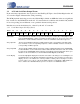
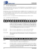
3.2.3 Status Data Port (Slot 2)
RD[15:0] Read Data. The RD[15:0] bits contain the register data requested by the controller from the
previous read request. All read requests will return the read address in the input Slot 1 and
the register data in the input Slot 2 on the following serial data frame.
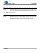
3.2.4 PCM Capture Data (Slot 3-10)
CD[17:0] Capture Data. The D[17:0] bits contain 18-bit PCM (2’s complement) capture data. The map-
ping of a given slot to an ADC is determined by the state of the ID[1:0] bits in the Extended
Audio ID Register (Index 28h) and the SM[1:0] and AMAP bits in the AC Mode Control Reg-
ister (Index 5Eh). The definition of each slot can be found in Table8 on page30.
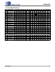
Bit 19 18 17 16 15 14 13 12 11 10 9 8 7 6 5 4 3 2 1 0
RD15 RD14 RD13 RD12 RD11 RD10 RD9 RD8 RD7 RD6 RD5 RD4 RD3 RD2 RD1 RD0 Reserved
Bit 19 18 17 16 15 14 13 12 11 10 9 8 7 6 5 4 3 2 1 0
CD17 CD16 CD15 CD14 CD13 CD12 CD11 CD10 CD9 CD8 CD7 CD6 CD5 CD4 CD3 CD2 CD1 CD0 0 0
DS319-BQPP2 17
CS4299-BQ