
User guide

34 DS686F1
CS4270
8.4 ADC and DAC Control - Address 04h
8.4.1 ADC High Pass Filter Freeze for CH A (Bit 7)
Function:
When this bit is set, the internal high-pass filter DC offset value for channel A are frozen.This value is con-
tinuously subtracted from the conversion result. To recalibrate ADC channel A and obtain a new or con-
tinuous value for the system DC offset, clear this bit. See “DC Offset Calibration Using the High-Pass
Filter” on page 23.
8.4.2 ADC High Pass Filter Freeze for CH B (Bit 6)
Function:
When this bit is set, the internal high-pass filter for channel B are frozen.The current DC offset value will
be static and continuously subtracted from the conversion. To recalibrate ADC channel A and obtain a
new or continuous value for the system DC offset, clear this bit. See “DC Offset Calibration Using the
High-Pass Filter” on page 23.
8.4.3 Digital Loopback (Bit 5)
Function:
When this bit is set, an internal digital loopback from the ADC to the DAC will be enabled. See Section
5.2.5 “Internal Digital Loopback” on page 23.
8.4.4 DAC Digital Interface Format (Bits 4:3)
Function:
The DAC_Digital_Interface_Format and the options are detailed in Table 11 and Figures 9–11.
8.4.5 ADC Digital Interface Format (Bit 0)
Function:
The required relationship between LRCK, SCLK, and SDOUT for the ADC is defined by the ADC Digital
Interface Format. The options are detailed in Table 12 and may be seen in Figures 9 and 10.
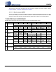
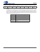
76543210
ADC_HPF_
FRZ_A
ADC_HPF_
FRZ_B
DIG_
LOOPBK
DAC_DIF1 DAC_DIF0 Reserved Reserved ADC_DIF0
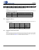
DAC_DIF1 DAC_DIF0 Description Format Figure
0 0 Left Justified, up to 24-bit data (default) 0 9
0 1 I²S, up to 24-bit data 1 10
1 1 Right-Justified, 16-bit Data 2 11
1 0 Right-Justified, 24-bit Data 3 11
Table 11. DAC Digital Interface Formats
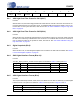
ADC_DIF Description Format Figure
0 Left Justified, up to 24-bit data (default) 0 9
1 I²S, up to 24-bit data 1 10
Table 12. ADC Digital Interface Formats