
User guide

32 DS686F1
CS4270
8. REGISTER DESCRIPTION
** All registers are read/write in I²C Mode and SPI Mode, unless otherwise noted**
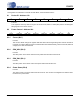
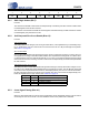
8.1 Device ID - Address 01h
Function:
This register is read only. Bits 7 through 4 are the device ID, which is 1100b (0Ch) and the remaining bits
REV[3:0] are for the device revision.
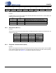
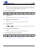
8.2 Power Control - Address 02h
8.2.1 Freeze (Bit 7)
Function:
This function allows changes to registers 05h–08h without the changes taking effect until the Freeze bit
is cleared. To make multiple changes to these bits take effect simultaneously, set the Freeze bit, make all
changes, then clear the Freeze bit.
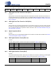
8.2.2 PDN_ADC (Bit 5)
Function:
The ADC portion of the device will enter a low-power state whenever this bit is set.
8.2.3 PDN_DAC (Bit 1)
Function:
The DAC portion of the device enters a low-power state when this bit is set.
8.2.4 Power Down (Bit 0)
Function:
The device enters a low-power state when this bit is set. The contents of all registers are retained when
the device is in power-down.
76543210
ID3 ID2 ID1 ID0 REV3 REV2 REV1 REV0
76543210
Freeze Reserved PDN_ADC Reserved Reserved Reserved PDN_DAC PDN