
User guide

DS686F1 31
CS4270
6.2.3 Memory Address Pointer (MAP)
The MAP byte comes after the address byte and selects the register to be read or written. Refer to
Figures 20 and 21 on page 29, and Figure 22 on page 30.
6.2.3.1 Map Increment (INCR)
The device has MAP auto increment capability enabled by the INCR bit (the MSB) of the MAP. If INCR is
set to 0, MAP will stay constant for successive I²C writes or reads and SPI writes. If INCR is set to 1, MAP
will auto increment after each byte is written, allowing block reads or writes of successive registers.
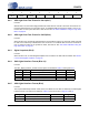
7. REGISTER QUICK REFERENCE
This table shows the register and register bit names and their associated default values.
Addr Function 7 6 5 4 3 2 1 0
01h Device ID ID3 ID2 ID1 ID0 REV3 REV2 REV1 REV0
p32 1100000 1
02h Power Control Freeze Reserved PDN_ADC Reserved Reserved Reserved PDN_DAC PDN
p32 0000000 0
03h Mode Control
Reserved Reserved FM1 FM0
MCLK_
FREQ2
MCLK_
FREQ1
MCLK_
FREQ0
POPG
p33 0011000 0
04h ADC and DAC
Control
ADC_HPF_
FRZ_A
ADC_HPF_
FRZ_B
DIG_
LOOPBK
DAC_DIF1 DAC_DIF0 Reserved Reserved ADC_DIF0
p34 0000000 0
05h Transition
Control
DAC_SNGL_
VOL
DAC_SOFT DAC_ZC
ADC_INV_
B
ADC_INV_
A
DAC_INV_
B
DAC_INV_A DE_EMPH
p35 0110000 0
06h Mute Control
Reserved Reserved
AUTO_
MUTE
MUTE_
ADC_CHB
MUTE_
ADC_CH A
MUTE_
POL
MUTE_DAC_
CHB
MUTE_DAC_
CHA
p36 0010000 0
07h DAC Channel A
Volume Control
DACA_
VOL7
DACA_
VOL6
DACA_
VOL5
DACA_
VOL4
DACA_
VOL3
DACA_
VOL2
DACA_
VOL1
DACA_
VOL0
p36 0000000 0
08h DAC Channel B
Volume Control
DACB_
VOL7
DACB_
VOL6
DACB_
VOL5
DACB_
VOL4
DACB_
VOL3
DACB_
VOL2
DACB_
VOL1
DACB_
VOL0
p37 0000000 0