
User guide

DS686F1 23
CS4270
5.2.5 Internal Digital Loopback
In Serial Control Port Mode, the CS4270 supports an internal digital loopback mode in which the output
of the ADC is routed to the input of the DAC. This mode may be activated by setting the DIG_LOOPBK
bit in the ADC and DAC Control register (04h).
When this bit is set, the CS4270 ignores the status of the DAC_DIF(4:3) bits in register 04h. Any changes
made to the DAC_DIF(4:3) bits while the DIG_LOOPBK bit is set will have no impact on operation until
the DIG_LOOPBK bit is released, at which time the Digital Interface Format of the DAC will operate ac-
cording to the format selected in the DAC_DIF(4:3) bits. While the DIG_LOOPBK bit is set, data will be
present on the SDOUT pin in the format selected in the ADC_DIF(0) bit in register 04h.
5.2.6 Auto-Mute
The Auto-Mute function is controlled by the status of the Auto Mute bit in the Mute register. When set, the
DAC output will mute following the reception of 8192 consecutive audio samples of static 0 or -1. A single
sample of non-static data will release the mute. Detection and muting are done independently for each
channel. The common mode on the output will be retained and the Mute Control pin for that channel will
become active during the mute period. The muting function is affected, similar to volume control changes,
by the Soft and Zero Cross bits in the Transition and Control register. The Auto Mute bit is set by default.
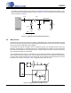
5.2.7 DC Offset Calibration Using the High-Pass Filter
At the system level, the input circuitry driving the CS4270 may generate a small DC offset level into the
A/D converter which could result in possibly yielding "clicks" when switching between devices in a multi-
channel system. The CS4270 includes one high-pass filter per channel (see “ADC High Pass Filter Freeze
for CH A (Bit 7)” on page 34 and “ADC High Pass Filter Freeze for CH A (Bit 7)” on page 34) to alleviate
this system problem.
Running the CS4270 with the high-pass filter enabled, then freezing the stored DC offset value eliminates
offsets anywhere in the signal path between the calibration point and the CS4270.
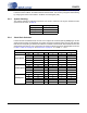
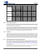
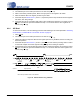
Slave Mode
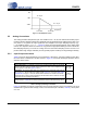
Speed Mode MCLK/LRCK SCLK/LRCK LRCK MCLK_FREQ2 MCLK_FREQ1 MCLK_FREQ0
Single-Speed
256 32, 48, 64, 128 Fs 0 0 0
384 32, 48, 64, 96, 128 Fs 0 0 1
512 32, 48, 64, 128 Fs 0 1 0
768 32, 48, 64, 96, 128 Fs 0 1 1
1,024 32, 48, 64, 96, 128 Fs 1 0 0
Double-Speed
128 32, 48, 64 Fs 0 0 0
192 32, 48, 64 Fs 0 0 1
256 32, 48, 64 Fs 0 1 0
384 32, 48, 64 Fs 0 1 1
512 32, 48, 64 Fs 1 0 0
Quad-Speed
64 32, 48, 64 Fs 0 0 0
96 32, 48, 64 Fs 0 0 1
128 32, 48, 64 Fs 0 1 0
192 32, 48, 64 Fs 0 1 1
256 32, 48, 64 Fs 1 0 0
Table 7. Clock Ratios - Serial Control Port Mode (Continued)