
User guide

20 DS686F1
CS4270
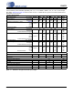
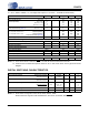
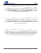
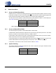
5.1.4 Clock Ratio Selection
Depending on whether the CS4270 is in Master or Slave Mode, different MCLK/LRCK and SCLK/LRCK
ratios may be used. These ratios are shown in the Table 4. ‘0’ = DGND, ‘1’ = VLC.
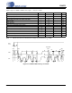
5.1.5 Interpolation Filter
In Stand-Alone Mode, the fast roll-off interpolation filter is used. Filter specifications can be found in Sec-
tion 4. Plots of the data are contained in Section 9. “Filter Plots” on page 38.
5.1.6 High-Pass Filter
At the system level, the input circuitry driving the CS4270 may generate a small DC offset into the ADC.
The CS4270 includes one high-pass filter per channel after the decimator to remove any DC offset, which
Master Mode
MCLK/LRCK SCLK/LRCK LRCK MDIV2 MDIV1
Single-Speed
256 64 Fs 0 0
384 (Note 22) 64 Fs 0 1
512 64 Fs 1 0
1,024 64 Fs 1 1
Double-Speed
128 64 Fs 0 0
192 (Note 22) 64 Fs 0 1
256 64 Fs 1 0
512 64 Fs 1 1
Quad-Speed
64 64 Fs 0 0
96 (Note 22) 64 Fs 0 1
128 64 Fs 1 0
256 64 Fs 1 1
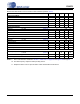
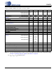
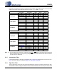
Slave Mode
MCLK/LRCK SCLK/LRCK LRCK MDIV2 MDIV1
Single-Speed
256 32, 48, 64, 128 Fs 0 0
384 (Note 22) 32, 48, 64, 96 Fs 0 1
512 32, 48, 64, 128 Fs 1 0
1,024 32, 48, 64, 96 Fs 1 1
Double-Speed
128 32, 48, 64 Fs 0 0
192 (Note 22) 32, 48, 64 Fs 0 1
256 32, 48, 64 Fs 1 0
512 32, 48, 64 Fs 1 1
Quad-Speed
64 32, 48, 64 Fs 0 0
96 (Note 22) 32, 48, 64 Fs 0 1
128 32, 48, 64 Fs 1 0
256 32, 48, 64 Fs 1 1
Table 4. Clock Ratios - Stand-Alone Mode
Note: 22. Once the MDIVx pins have been configured for this setting, RST must be asserted and then deasserted
before normal operation can begin. During startup, RST
should remain asserted until after this selection
is made and then deasserted.