
User guide

DS686F1 17
CS4270
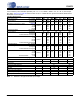
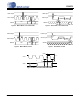
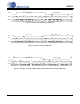
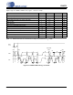
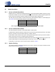
SWITCHING CHARACTERISTICS - SOFTWARE MODE - I²C FORMAT
Inputs: Logic ‘0’ = AGND = DGND = 0 V, Logic ‘1’ = VLC, C
L
=30pF
Note: 17. Data must be held for sufficient time to bridge the transition time, t
fc
, of SCL.
Parameter Symbol Min Max Unit
SCL Clock Frequency f
scl
- 100 kHz
RST
Rising Edge to Start t
irs
500 - ns
Bus Free Time Between Transmissions t
buf
4.7 - µs
Start Condition Hold Time (prior to first clock pulse) t
hdst
4.0 - µs
Clock Low time t
low
4.7 - µs
Clock High Time t
high
4.0 - µs
Setup Time for Repeated Start Condition t
sust
4.7 - µs
SDA Hold Time from SCL Falling (Note 17) t
hdd
0-µs
SDA Setup time to SCL Rising t
sud
250 - ns
Rise Time of SCL and SDA t
rc
-1µs
Fall Time SCL and SDA t
fc
-300ns
Setup Time for Stop Condition t
susp
4.7 - µs
Acknowledge Delay from SCL Falling t
ack
300 1000 ns
t
buf
t
hdst
t
low
t
hdd
t
high
t
sud
Stop Start
SDA
SCL
t
irs
RST
t
hdst
t
rc
t
fc
t
sust
t
susp
Start
Stop
Repeated
t
rd
t
fd
t
ack
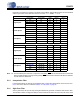
Figure 12. Software Mode Timing - I²C Format