
User guide

14 DS686F1
CS4270
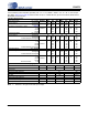
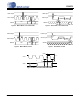
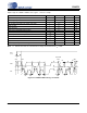
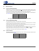
SWITCHING CHARACTERISTICS - SERIAL AUDIO INTERFACE
Logic "0" = DGND = AGND = 0 V; Logic "1" = VD, C
L
= 20 pF.
Notes: 15. In Control Port Mode, MCLK Frequency, and Functional Mode Select bits must be configured according
to Table 7 on page 22, Table 9 on page 33, and Table 13 on page 35.
16. t
sclkw
=
t
sclkh
+
t
sclkl
in Figures 5 and 7.
Parameter Symbol Min Typ Max Unit
Sample Rate Single-Speed Mode
Double-Speed Mode
Quad-Speed Mode
Fs
Fs
Fs
4
50
100
-
-
-
54
108
216
kHz
kHz
kHz
MCLK Specifications
MCLK Frequency Stand-Alone Mode
(Note 15) Serial Control Port Mode
fmclk
fmclk
1.024
1.024
-
-
55.296
55.296
MHz
MHz
MCLK Duty Cycle 405060ns
Master Mode
LRCK Duty Cycle - 50 - %
SCLK Period (Note 16) t
sclkw
--s
SCLK Duty Cycle - 50 - %
SCLK falling to LRCK edge t
mslr
-20 - 20 ns
SCLK falling to SDOUT valid t
sdo
- - 32 ns
SDIN valid to SCLK rising setup time t
sdis
16 - - ns
SCLK rising to SDIN hold time t
sdih
20 - - ns
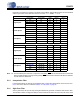
Slave Mode
LRCK Duty Cycle 40 50 60 %
SCLK Period
(Note 15) Single-Speed Mode
Double-Speed Mode
Quad-Speed Mode
t
sclkw
t
sclkw
t
sclkw
-
-
-
-
-
-
s
s
s
SCLK Duty Cycle 455055ns
SCLK falling to LRCK edge t
slrd
-20 - 20 ns
SDOUT valid before SCLK rising t
stp
10 - - ns
SDOUT valid after SCLK rising t
hld
5--ns
SDIN valid to SCLK rising setup time t
sdis
16 - - ns
SCLK rising to SDIN hold time t
sdih
20 - - ns
1
64Fs
------------------
1
128Fs
---------------------
1
64Fs
------------------
1
64Fs
------------------