
User guide

DS686F1 13
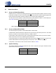
CS4270
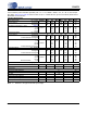
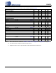
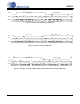
DC ELECTRICAL CHARACTERISTICS
T
A
= 25° C; AGND = DGND = 0 V, all voltages with respect to 0 V; MCLK = 12.288 MHz; Master Mode).
Notes: 12. Power Down Mode is defined as RST
= Low with all clocks and data lines held static.
13. Valid with the recommended capacitor values on FILT+ and VQ as shown in the Typical Connection
Diagram.
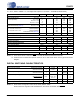
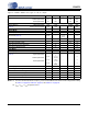
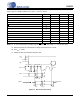
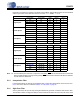
DIGITAL SWITCHING CHARACTERISTICS
Notes: 14. Serial Audio Port signals include: SCLK, LRCK, SDOUT, SDIN
Serial Control Port signals include: SDA/CDOUT, SCL/CCLK, AD1/CDIN, AD0/CS
, RST
Parameter Symbol Min Typ Max Unit
Power Supply
Power Supply Current VA = 5 V
(Normal Operation) VA = 3.3 V
VD, VLC = 5 V
VD, VLC = 3.3 V
I
A
I
A
I
D
I
D
-
-
-
-
37
24
32
13
42
30
38
20
mA
mA
mA
mA
Power Supply Current VA = 5 V
(Power-Down Mode) (Note 12) VD, VLC = 5 V
I
A
I
D
-
-
70
3
-
-
A
A
Power Consumption
VA = 5 V, VD = VLC= 3.3 V Normal Operation
VA = 5 V, VD = VLC = 5 V Normal Operation
Power-Down Mode (Note 12)
-
-
-
-
-
-
224
345
365
270
400
-
mW
mW
W
Power Supply Rejection Ratio(1 kHz) (Note 13) PSRR - 55 - dB
Common Mode Voltage
Nominal Common Mode Voltage VQ - VA/2 - VDC
Maximum DC Current Source/Sink from VQ - 1 - A
VQ Output Impedance - 25 - k
Positive Voltage Reference
FILT+ Nominal Voltage FILT+ - VA - VDC
Maximum DC Current Source/Sink from FILT+ - 10 - A
FILT+ Output Impedance - 10 - k
Mute Control
Maximum MUTEA & MUTEB Drive Current - 3 - mA
Parameter (Note 14) Symbol Min Typ Max Units
High-Level Input Voltage Serial Audio Interface
Serial Control Port
V
IH
0.7xVD
0.7xVLC
-
-
-
-
V
V
Low-Level Input Voltage Serial Audio Interface
Serial Control Port
V
IL
-
-
-
-
0.2xVD
0.2xVLC
V
V
High-Level Output Voltage at I
o
= 2 mA Serial Audio Interface
Serial Control Port
MUTEA
, MUTEB
V
OH
VD - 1.0
VLC - 1.0
VA - 1.0
-
-
-
-
-
-
V
V
V
Low-Level Output Voltage at I
o
= 2 mA
V
OL
--0.4V
Input Leakage Current I
in
-10 - 10 A