
Instruction Manual

56 DS657F3
CS4265
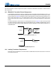
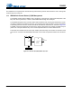
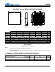
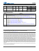
12.PACKAGE DIMENSIONS
Notes:
1. Dimensioning and tolerance per ASME Y 14.5M-1995.
2. Dimensioning lead width applies to the plated terminal and is measured between 0.20 mm and 0.25 mm
from the terminal tip.
13.THERMAL CHARACTERISTICS AND SPECIFICATIONS
INCHES MILLIMETERS NOTE
DIM MIN NOM MAX MIN NOM MAX
A----0.0394----1.001
A1 0.0000 -- 0.0020 0.00 -- 0.05 1
b 0.0071 0.0091 0.0110 0.18 0.23 0.28 1,2
D 0.1969 BSC 5.00 BSC 1
D2 0.1280 0.1299 0.1319 3.25 3.30 3.35 1
E 0.1969 BSC 5.00 BSC 1
E2 0.1280 0.1299 0.1319 3.25 3.30 3.35 1
e 0.0197 BSC 0.50 BSC 1
L 0.0118 0.0157 0.0197 0.30 0.40 0.50 1
JEDEC #: MO-220
Controlling Dimension is Millimeters.
Parameters Symbol Min Typ Max Units
Package Thermal Resistance 2 Layer Board
4 Layer Board
JA
-
-
52
38
-
-
°C/Watt
°C/Watt
Allowable Junction Temperature
--125
C
Side View
A1
Bottom View
Top View
A
Pin #1 Corner
D
E
D2
L
b
e Pin #1 Corner
E2
32L QFN (5 X 5 mm BODY) PACKAGE DRAWING