
Instruction Manual


DS657F3 45
CS4265
6.18 Transmitter Control 2 - Address 12h
6.18.1 Transmitter Digital Interface Format (Bits 7:6)
Function:
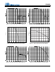
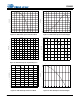
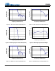
The required relationship between LRCK, SCLK and SDIN for the transmitter is defined by the Transmitter
Digital Interface Format and the options are detailed in Table 18 and Figures 5-7.
6.18.2 Transmitter Output Driver Control (Bit 5)
Function:
When this bit is cleared, the transmitter output pin driver will be in the normal operational mode. When
set, the transmitter output pin driver will drive to a constant 0 V.
6.18.3 Transmitter Mute Control (Bit 4)
Function:
When this bit is cleared, the transmitter data will be in the normal operational mode. When set, the trans-
mitter will output all zero data.
6.18.4 Transmitted Validity Bit Control (Bit 3)
Function:
This bit sets the transmitted Validity bit level.
When this bit is cleared, valid linear PCM audio data is indicated. When this bit is set, invalid or non-linear
PCM audio data is indicated.
6.18.5 Transmitter Mono/Stereo Operation Control (Bit 2)
Function:
When this bit is cleared, the transmitter will operate in stereo mode. When set, the transmitter will operate
in Mono Mode with one input channel’s data output in both A and B subframes (see “IEC60958-3 Channel
Status (C) Bit Management” on page 53) and the CS data defined by the MMTCS bit (see Section 6.18.6).
6.18.6 Mono Mode CS Data Source (Bit 1)
Function:
When this bit is cleared, the transmitter will transmit the channel A CS data in the A subframe and the
channel B CS data in the B subframe.
When this bit is set, the transmitter will transmit the CS data defined for the channel selected by the
MMTLR bit in both the A and B subframes.
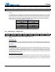
76543210
Tx_DIF1 Tx_DIF0 TxOff TxMute V MMT MMTCS MMTLR
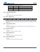
Tx_DIF1 Tx_DIF0 Description Format Figure
0 0 Left Justified, up to 24-bit data (default) 0 5
0 1 I²S, up to 24-bit data 1 6
1 0 Right-Justified, 16-bit Data 2 7
1 1 Right-Justified, 24-bit Data 3 7
Table 18. Transmitter Digital Interface Formats