
Instruction Manual


DS657F3 39
CS4265
6.4.3 Mute ADC (Bit 2)
Function:
When this bit is set, the serial audio output of the both ADC channels is muted.
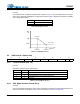
6.4.4 ADC High-Pass Filter Freeze (Bit 1)
Function:
When this bit is set, the internal high-pass filter is disabled. The current DC offset value will be frozen and
continue to be subtracted from the conversion result. See “High-Pass Filter and DC Offset Calibration” on
page 25.
6.4.5 Master / Slave Mode (Bit 0)
Function:
This bit selects either master or slave operation for the serial audio port. Setting this bit selects Master
Mode, while clearing this bit selects Slave Mode.
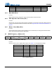
6.5 MCLK Frequency - Address 05h
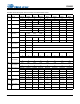
6.5.1 Master Clock Dividers (Bits 6:4)
Function:
Sets the frequency of the supplied MCLK signal. See Table 11 for the appropriate settings.
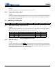
ADC_DIF Description Format Figure
0 Left-Justified, up to 24-bit data (default) 0 5
1 I²S, up to 24-bit data 1 6
Table 10. ADC Digital Interface Formats
76543210
Reserved
MCLK
Freq2
MCLK
Freq1
MCLK
Freq0
Reserved Reserved Reserved Reserved
MCLK Divider MCLK Freq2 MCLK Freq1 MCLK Freq0
÷1 000
÷1.5 001
÷2 010
÷3 011
÷4 100
Reserved 101
Reserved 11x
Table 11. MCLK Frequency