
Instruction Manual

24 DS657F3
CS4265
4. APPLICATIONS
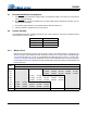
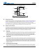
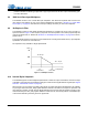
4.1 Recommended Power-Up Sequence
1. Hold RESET low until the power supply, MCLK, and LRCK are stable. In this state, the Control Port is
reset to its default settings.
2. Bring RESET
high. The device will remain in a low power state with the PDN bit set by default. The con-
trol port will be accessible.
3. The desired register settings can be loaded while the PDN bit remains set.
4. Clear the PDN bit to initiate the power-up sequence.
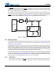
4.2 System Clocking
The CS4265 will operate at sampling frequencies from 4 kHz to 200 kHz. This range is divided into three
speed modes as shown in Table 1.
4.2.1 Master Clock
MCLK/LRCK must maintain an integer ratio as shown in Table 2. The LRCK frequency is equal to Fs, the
frequency at which audio samples for each channel are clocked into or out of the device. The FM bits (See
“Functional Mode (Bits 7:6)” on page 38.) and the MCLK Freq bits (See “MCLK Frequency - Address 05h”
on page 39.) configure the device to generate the proper clocks in Master Mode, and receive the proper
clocks in Slave Mode. Table 2 illustrates several standard audio sample rates and the required MCLK and
LRCK frequencies.
Mode Sampling Frequency
Single-Speed 4-50 kHz
Double-Speed 50-100 kHz
Quad-Speed 100-200 kHz
Table 1. Speed Modes
LRCK
(kHz)
MCLK (MHz)
64x 96x 128x 192x 256x 384x 512x 768x 1024x
32
- ---8.1920 12.2880 16.3840 24.5760 32.7680
44.1
- ---11.2896 16.9344 22.5792 33.8680 45.1584
48
- ---12.2880 18.4320 24.5760 36.8640 49.1520
64
- - 8.1920 12.2880 16.3840 24.5760 32.7680 - -
88.2
- - 11.2896 16.9344 22.5792 33.8680 45.1584 - -
96
- - 12.2880 18.4320 24.5760 36.8640 49.1520 - -
128
8.1920 12.2880 16.3840 24.5760 32.7680 - - - -
176.4
11.2896 16.9344 22.5792 33.8680 45.1584 - - - -
192
12.2880 18.4320 24.5760 36.8640 49.1520 - - - -
Mode
QSM
DSM
SSM
Table 2. Common Clock Frequencies