
Instruction Manual

DS657F3 17
CS4265
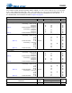
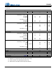
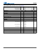
DC ELECTRICAL CHARACTERISTICS
AGND = DGND = 0 V, all voltages with respect to ground. MCLK=12.288 MHz; Fs=48 kHz; Master Mode.
18. Power-Down Mode is defines as RESET
= Low with all clock and data lines held static and no analog
input.
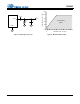
19. Valid with the recommended capacitor values on FILT+ and VQ as shown in the Typical Connection
Diagram.
20. Guaranteed by design. The DC current draw represents the allowed current draw due to typical leakage
through the electrolytic de-coupling capacitors.
Parameter Symbol Min Typ Max Unit
Power Supply Current VA = 5 V
(Normal Operation) VA = 3.3 V
VD, VLS, VLC = 5 V
VD, VLS, VLC = 3.3 V
I
A
I
A
I
D
I
D
-
-
-
-
41
37
39
23
50
45
47
28
mA
mA
mA
mA
Power Supply Current VA = 5 V
(Power-Down Mode) (Note 18) VLS, VLC, VD=5 V
I
A
I
D
-
-
0.50
0.54
-
-
mA
mA
Power Consumption
(Normal Operation) VA, VD, VLS, VLC = 5 V
VA, VD, VLS, VLC = 3.3 V
(Power-Down Mode) VA, VD, VLS, VLC = 5 V
-
-
-
-
-
-
400
198
4.2
485
241
-
mW
mW
mW
Power Supply Rejection Ratio (1 kHz) (Note 19) PSRR - 55 - dB
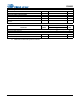
VQ Characteristics
Quiescent Voltage VQ - 0.5 x VA - VDC
DC Current from VQ (Note 20) I
Q
-- 1A
VQ Output Impedance Z
Q
-4.5 -k
FILT+ Nominal Voltage FILT+ - VA - VDC
Microphone Bias Voltage MICBIAS - 0.8 x VA - VDC
Current from MICBIAS I
MB
-- 2mA