
User guide
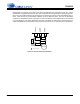
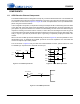
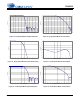
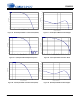
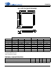
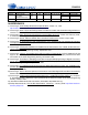
Table Of Contents
- 1. Characteristics and Specifications
- Specified Operating Conditions
- Absolute Maximum Ratings
- Analog Input Characteristics
- A/D Digital Filter Characteristics
- Analog Output Characteristics
- D/A Digital Filter Characteristics
- Switching Characteristics
- Switching Characteristics - Control Port - I²C™ Format
- Switching Characteristics - Control Port - SPI™ Format
- DC Electrical Characteristics
- Digital Interface Characteristics
- 2. Pin Descriptions
- 3. Typical Connection Diagram
- 4. Applications
- 4.1 Overview
- 4.2 Analog Inputs
- 4.3 Analog Outputs
- 4.4 S/PDIF Receiver
- 4.5 Clock Generation
- 4.6 Digital Interfaces
- 4.7 Control Port Description and Timing
- 4.8 Interrupts
- 4.9 Reset and Power-Up
- 4.10 Power Supply, Grounding, and PCB Layout
- 5. Register Quick Reference
- 6. Register Description
- Table 5. DAC De-Emphasis
- Table 6. Receiver De-Emphasis
- Table 7. Digital Interface Formats
- Table 8. ADC One-Line Mode
- Table 9. DAC One-Line Mode
- Table 10. RMCK Divider Settings
- Table 11. OMCK Frequency Settings
- Table 12. Master Clock Source Select
- Table 13. AES Format Detection
- Table 14. Receiver Clock Frequency Detection
- Table 15. Example Digital Volume Settings
- Table 16. ATAPI Decode
- Table 17. Example ADC Input Gain Settings
- Table 18. TXP Output Selection
- Table 19. Receiver Input Selection
- Table 20. Auxiliary Data Width Selection
- 7. Parameter Definitions
- 8. Appendix A: External Filters
- 9. Appendix B: S/PDIF Receiver
- 10. Appendix C: PLL Filter
- 11. Appendix D: External AES3-S/PDIF-IEC60958 Receiver Components
- 12. Appendix E: ADC Filter Plots
- Figure 34. Single-Speed Mode Stopband Rejection
- Figure 35. Single-Speed Mode Transition Band
- Figure 36. Single-Speed Mode Transition Band (Detail)
- Figure 37. Single-Speed Mode Passband Ripple
- Figure 38. Double-Speed Mode Stopband Rejection
- Figure 39. Double-Speed Mode Transition Band
- Figure 40. Double-Speed Mode Transition Band (Detail)
- Figure 41. Double-Speed Mode Passband Ripple
- Figure 42. Quad-Speed Mode Stopband Rejection
- Figure 43. Quad-Speed Mode Transition Band
- Figure 44. Quad-Speed Mode Transition Band (Detail)
- Figure 45. Quad-Speed Mode Passband Ripple
- 13. Appendix F: DAC Filter Plots
- Figure 46. Single-Speed (fast) Stopband Rejection
- Figure 47. Single-Speed (fast) Transition Band
- Figure 48. Single-Speed (fast) Transition Band (detail)
- Figure 49. Single-Speed (fast) Passband Ripple
- Figure 50. Single-Speed (slow) Stopband Rejection
- Figure 51. Single-Speed (slow) Transition Band
- Figure 52. Single-Speed (slow) Transition Band (detail)
- Figure 53. Single-Speed (slow) Passband Ripple
- Figure 54. Double-Speed (fast) Stopband Rejection
- Figure 55. Double-Speed (fast) Transition Band
- Figure 56. Double-Speed (fast) Transition Band (detail)
- Figure 57. Double-Speed (fast) Passband Ripple
- Figure 58. Double-Speed (slow) Stopband Rejection
- Figure 59. Double-Speed (slow) Transition Band
- Figure 60. Double-Speed (slow) Transition Band (detail)
- Figure 61. Double-Speed (slow) Passband Ripple
- Figure 62. Quad-Speed (fast) Stopband Rejection
- Figure 63. Quad-Speed (fast) Transition Band
- Figure 64. Quad-Speed (fast) Transition Band (detail)
- Figure 65. Quad-Speed (fast) Passband Ripple
- Figure 66. Quad-Speed (slow) Stopband Rejection
- Figure 67. Quad-Speed (slow) Transition Band
- Figure 68. Quad-Speed (slow) Transition Band (detail)
- Figure 69. Quad-Speed (slow) Passband Ripple
- 14. Package Dimensions
- 15. Ordering Information
- 16. References
- 17. Revision History
90 DS583F2
CS42516
15.ORDERING INFORMATION
16.REFERENCES
1) Cirrus Logic, Audio Quality Measurement Specification, Version 1.0, 1997.
http://www.cirrus.com/products/papers/meas/meas.html
2) Cirrus Logic, AN18: Layout and Design Rules for Data Converters and Other Mixed Signal Devices
,
Version 6.0, February 1998.
3) Cirrus Logic, AN22: Overview of Digital Audio Interface Data Structures
, Version 2.0, February 1998.;
A useful tutorial on digital audio specifications.
4) Cirrus Logic, AN134: AES and S/PDIF Recommended Transformers
, Version 2, April 1999.
5) Cirrus Logic, An Understanding and Implementation of the SCMS Serial Copy Management System
for Digital Audio Transmission, by Clifton Sanchez.; an excellent tutorial on SCMS. It is available from
the AES as preprint 3518.
6) Cirrus Logic, Techniques to Measure and Maximize the Performance of a 120 dB, 96 kHz A/D Con-
verter Integrated Circuit, by Steven Harris, Steven Green and Ka Leung. Presented at the 103rd Con-
vention of the Audio Engineering Society, September 1997.
7) Cirrus Logic, A Stereo 16-bit Delta-Sigma A/D Converter for Digital Audio
, by D.R. Welland, B.P. Del
Signore, E.J. Swanson, T. Tanaka, K. Hamashita, S. Hara, K. Takasuka. Paper presented at the 85th
Convention of the Audio Engineering Society, November 1988.
8) Cirrus Logic, The Effects of Sampling Clock Jitter on Nyquist Sampling Analog-to-Digital Converters,
and on Oversampling Delta Sigma ADC's, by Steven Harris. Paper presented at the 87th Convention
of the Audio Engineering Society, October 1989.
9) Cirrus Logic, An 18-Bit Dual-Channel Oversampling Delta-Sigma A/D Converter, with 19-Bit Mono Ap-
plication Example, by Clif Sanchez. Paper presented at the 87th Convention of the Audio Engineering
Society, October 1989.
10) Cirrus Logic, How to Achieve Optimum Performance from Delta-Sigma A/D and D/A Converters
,by
Steven Harris. Presented at the 93rd Convention of the Audio Engineering Society, October 1992.
11) Cirrus Logic, A Fifth-Order Delta-Sigma Modulator with 110 dB Audio Dynamic Range
, by I. Fujimori,
K. Hamashita and E.J. Swanson. Paper presented at the 93rd Convention of the Audio Engineering
Society, October 1992.
12) International Electrotechnical Commission, IEC60958, http://www.ansi.org
13) Philips Semiconductor, The I2C-Bus Specification: Version 2.1
, January 2000. http://www.semicon-
ductors.philips.com
Product Description Package Pb-Free Grade Temp Range Container Order #
CS42516 110 dB, 192 kHz
6-Ch Codec
with S/PDIF Receiver
64-pin
LQFP
Yes Commercial -10° to +70° C Tray CS42516-CQZ
Tape & Reel CS42516-CQZR
CDB42518 CS42516 Evaluation Board No - - - CDB42518