
User guide
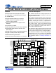
Table Of Contents
- 1. Characteristics and Specifications
- Specified Operating Conditions
- Absolute Maximum Ratings
- Analog Input Characteristics
- A/D Digital Filter Characteristics
- Analog Output Characteristics
- D/A Digital Filter Characteristics
- Switching Characteristics
- Switching Characteristics - Control Port - I²C™ Format
- Switching Characteristics - Control Port - SPI™ Format
- DC Electrical Characteristics
- Digital Interface Characteristics
- 2. Pin Descriptions
- 3. Typical Connection Diagram
- 4. Applications
- 4.1 Overview
- 4.2 Analog Inputs
- 4.3 Analog Outputs
- 4.4 S/PDIF Receiver
- 4.5 Clock Generation
- 4.6 Digital Interfaces
- 4.7 Control Port Description and Timing
- 4.8 Interrupts
- 4.9 Reset and Power-Up
- 4.10 Power Supply, Grounding, and PCB Layout
- 5. Register Quick Reference
- 6. Register Description
- Table 5. DAC De-Emphasis
- Table 6. Receiver De-Emphasis
- Table 7. Digital Interface Formats
- Table 8. ADC One-Line Mode
- Table 9. DAC One-Line Mode
- Table 10. RMCK Divider Settings
- Table 11. OMCK Frequency Settings
- Table 12. Master Clock Source Select
- Table 13. AES Format Detection
- Table 14. Receiver Clock Frequency Detection
- Table 15. Example Digital Volume Settings
- Table 16. ATAPI Decode
- Table 17. Example ADC Input Gain Settings
- Table 18. TXP Output Selection
- Table 19. Receiver Input Selection
- Table 20. Auxiliary Data Width Selection
- 7. Parameter Definitions
- 8. Appendix A: External Filters
- 9. Appendix B: S/PDIF Receiver
- 10. Appendix C: PLL Filter
- 11. Appendix D: External AES3-S/PDIF-IEC60958 Receiver Components
- 12. Appendix E: ADC Filter Plots
- Figure 34. Single-Speed Mode Stopband Rejection
- Figure 35. Single-Speed Mode Transition Band
- Figure 36. Single-Speed Mode Transition Band (Detail)
- Figure 37. Single-Speed Mode Passband Ripple
- Figure 38. Double-Speed Mode Stopband Rejection
- Figure 39. Double-Speed Mode Transition Band
- Figure 40. Double-Speed Mode Transition Band (Detail)
- Figure 41. Double-Speed Mode Passband Ripple
- Figure 42. Quad-Speed Mode Stopband Rejection
- Figure 43. Quad-Speed Mode Transition Band
- Figure 44. Quad-Speed Mode Transition Band (Detail)
- Figure 45. Quad-Speed Mode Passband Ripple
- 13. Appendix F: DAC Filter Plots
- Figure 46. Single-Speed (fast) Stopband Rejection
- Figure 47. Single-Speed (fast) Transition Band
- Figure 48. Single-Speed (fast) Transition Band (detail)
- Figure 49. Single-Speed (fast) Passband Ripple
- Figure 50. Single-Speed (slow) Stopband Rejection
- Figure 51. Single-Speed (slow) Transition Band
- Figure 52. Single-Speed (slow) Transition Band (detail)
- Figure 53. Single-Speed (slow) Passband Ripple
- Figure 54. Double-Speed (fast) Stopband Rejection
- Figure 55. Double-Speed (fast) Transition Band
- Figure 56. Double-Speed (fast) Transition Band (detail)
- Figure 57. Double-Speed (fast) Passband Ripple
- Figure 58. Double-Speed (slow) Stopband Rejection
- Figure 59. Double-Speed (slow) Transition Band
- Figure 60. Double-Speed (slow) Transition Band (detail)
- Figure 61. Double-Speed (slow) Passband Ripple
- Figure 62. Quad-Speed (fast) Stopband Rejection
- Figure 63. Quad-Speed (fast) Transition Band
- Figure 64. Quad-Speed (fast) Transition Band (detail)
- Figure 65. Quad-Speed (fast) Passband Ripple
- Figure 66. Quad-Speed (slow) Stopband Rejection
- Figure 67. Quad-Speed (slow) Transition Band
- Figure 68. Quad-Speed (slow) Transition Band (detail)
- Figure 69. Quad-Speed (slow) Passband Ripple
- 14. Package Dimensions
- 15. Ordering Information
- 16. References
- 17. Revision History
4 DS583F2
CS42516
11. APPENDIX D: EXTERNAL AES3-S/PDIF-IEC60958 RECEIVER COMPONENTS .......................... 82
11.1 AES3 Receiver External Components .......................................................................................... 82
12. APPENDIX E: ADC FILTER PLOTS .................................................................................................. 83
13. APPENDIX F: DAC FILTER PLOTS .................................................................................................. 85
14. PACKAGE DIMENSIONS ............................................................................................................... 89
THERMAL CHARACTERISTICS .......................................................................................................... 89
15. ORDERING INFORMATION .............................................................................................................. 90
16. REFERENCES .................................................................................................................................... 90
17. REVISION HISTORY ......................................................................................................................... 91
LIST OF FIGURES
Figure 1. Serial Audio Port Master Mode Timing ...................................................................................... 11
Figure 2. Serial Audio Port Slave Mode Timing ........................................................................................ 11
Figure 3. Control Port Timing - I²C Format ................................................................................................ 12
Figure 4. Control Port Timing - SPI Format ............................................................................................... 13
Figure 5. Typical Connection Diagram ...................................................................................................... 19
Figure 6. Full-Scale Analog Input .............................................................................................................. 20
Figure 7. Full-Scale Output ....................................................................................................................... 21
Figure 8. ATAPI Block Diagram (x = channel pair 1, 2, or 3) ....................................................................22
Figure 9. CS42516 Clock Generation ....................................................................................................... 24
Figure 10. I²S Serial Audio Formats .......................................................................................................... 28
Figure 11. Left-Justified Serial Audio Formats .......................................................................................... 29
Figure 12. Right-Justified Serial Audio Formats ........................................................................................ 29
Figure 13. One Line Mode #1 Serial Audio Format ................................................................................... 30
Figure 14. One Line Mode #2 Serial Audio Format ................................................................................... 30
Figure 15. ADCIN1/ADCIN2 Serial Audio Format ..................................................................................... 31
Figure 16. OLM Configuration #1 .............................................................................................................. 32
Figure 17. OLM Configuration #2 .............................................................................................................. 33
Figure 18. OLM Configuration #3 .............................................................................................................. 34
Figure 19. OLM Configuration #4 .............................................................................................................. 35
Figure 20. OLM Configuration #5 .............................................................................................................. 36
Figure 21. Control Port Timing in SPI Mode ............................................................................................. 37
Figure 22. Control Port Timing, I²C Write .................................................................................................. 38
Figure 23. Control Port Timing, I²C Read .................................................................................................. 38
Figure 24. Recommended Analog Input Buffer ......................................................................................... 73
Figure 25. Recommended Analog Output Buffer ...................................................................................... 73
Figure 26. Channel Status Data Buffer Structure ...................................................................................... 75
Figure 27. PLL Block Diagram .................................................................................................................. 77
Figure 28. Jitter-Attenuation Characteristics of PLL - Configurations 1 & 2 .............................................. 79
Figure 29. Jitter-Attenuation Characteristics of PLL - Configuration 3 ...................................................... 79
Figure 30. Recommended Layout Example .............................................................................................. 81
Figure 31. Consumer Input Circuit ............................................................................................................ 82
Figure 32. S/PDIF MUX Input Circuit ........................................................................................................ 82
Figure 33. TTL/CMOS Input Circuit ........................................................................................................... 82
Figure 34. Single-Speed Mode Stopband Rejection ................................................................................. 83
Figure 35. Single-Speed Mode Transition Band ....................................................................................... 83
Figure 36. Single-Speed Mode Transition Band (Detail) ........................................................................... 83
Figure 37. Single-Speed Mode Passband Ripple ..................................................................................... 83
Figure 38. Double-Speed Mode Stopband Rejection ................................................................................83
Figure 39. Double-Speed Mode Transition Band ...................................................................................... 83
Figure 40. Double-Speed Mode Transition Band (Detail) ......................................................................... 84
Figure 41. Double-Speed Mode Passband Ripple .................................................................................... 84
Figure 42. Quad-Speed Mode Stopband Rejection ..................................................................................84