
User Manual


8 DS656F3
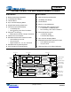
CS4245
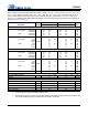
AGND 13 Analog Ground (Input) - Ground reference for the internal analog section.
VA 14 Analog Power (Input) - Positive power for the internal analog section.
AFILTA 15 Antialias Filter Connection (Output) - Antialias filter connection for the channel A ADC input.
AFILTB 16 Antialias Filter Connection (Output) - Antialias filter connection for the channel B ADC input.
VQ1 17 Quiescent Voltage 1 (Output) - Filter connection for the internal quiescent reference voltage.
VQ2 18 Quiescent Voltage 2 (Output) - Filter connection for the internal quiescent reference voltage.
FILT1+ 19 Positive Voltage Reference 1 (Output) - Positive reference voltage for the internal sampling circuits.
FILT2+ 20 Positive Voltage Reference 2 (Output) - Positive reference voltage for the internal sampling circuits.
AIN4A/MICIN1
AIN4B/MICIN2
21, 22
Stereo Analog Input 4 / Microphone Input 1 & 2 (Input) - The full-scale level is specified in the ADC
Analog Characteristics specification table.
AIN5A
AIN5B
23, 24
Stereo Analog Input 5 (Input) - The full-scale level is specified in the ADC Analog Characteristics
specification table.
MICBIAS 25
Microphone Bias Supply (Output) - Low-noise bias supply for external microphone. Electrical charac-
teristics are specified in the DC Electrical Characteristics specification table.
AIN6A
AIN6B
26, 27
Stereo Analog Input 6 (Input) - Th
e full-scale level is specified in the ADC Analog Characteristics
specification table.
AUXOUTA
AUXOUTB
28, 29
Auxiliary Analog Audio Output (Output) - Analog output from either the DAC, the PGA block, or high
impedance. See “Auxiliary Output Source Select (Bits 6:5)” on page 46.
VA 30 Analog Power (Input) - Positive power for the internal analog section.
AGND 31, 32 Analog Ground (Input) - Ground reference for the internal analog section.
AOUTA
AOUTB
33, 34
DAC Analog Audio Output (Output) - The full-scale output level is specified in the DAC Analog Char-
acteristics specification table.
MUTEC
35
Mute Control (Output) - This pin is active during power-up initialization, reset, muting, when master
clock to left/right clock frequency ratio is incorrect, or power-down.
VLS 36
Serial Audio Interface Power (Input) - Determines the required signal level for the serial audio inter-
face. Refer to the Recommended Operating Conditions for appropriate voltages.
SDIN 37 Serial Audio Data Input (Input) - Input for two’s complement serial audio data.
SCLK2 38 Serial Port 2 Serial Bit Clock (Input/Output) - Serial bit clock for serial audio interface 2.
LRCK2 39
Serial Port 2 Left Right Clock (Input/Output) - Determines which channel, Left or Right, is currently
active on the serial audio input data line.
MCLK2 40 Master Clock 2 (Input) - Optional asynchronous clock source for the DAC’s delta-sigma modulators.
SDOUT 41 Serial Audio Data Output (Output) - Output for two’s complement serial audio data.
SCLK1 42 Serial Port 1 Serial Bit Clock (Input/Output) - Serial bit clock for serial audio interface 1.
LRCK1 43
Serial Port 1 Left Right Clock (Input/Output) - Determines which channel, Left or Right, is currently
active on the serial audio output data line.
MCLK1 44
Master Clock 1 (Input) - Clock source for the ADC’s delta-sigma modulators. By default, this signal
also clocks the DAC’s delta-sigma modulators.
DGND 45 Digital Ground (Input) - Ground reference for the internal digital section.
VD 46 Digital Power (Input) - Positive power for the internal digital section.
INT 47 Interrupt (Output) - Indicates an interrupt condition has occurred.
OVFL 48 ADC Overflow (Output) - Indicates an ADC overflow condition is present.