
User Manual


24 DS656F3
CS4245
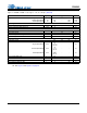
SWITCHING CHARACTERISTICS - SERIAL AUDIO PORT 2
Logic ‘0’ = DGND = AGND = 0 V; Logic ‘1’ = VL, C
L
= 20 pF. (Note 29)
29. See Figure 5 and Figure 6 on page 25.
Parameter Symbol Min Typ Max Unit
Sample Rate Single Speed Mode
Double Speed Mode
Quad Speed Mode
Fs
Fs
Fs
4
50
100
-
-
-
50
100
200
kHz
kHz
kHz
MCLK Specifications
MCLK2 Input Frequency fmclk 1.024 - 51.200 MHz
MCLK2 Input Pulse Width High/Low t
clkhl 8--ns
Master Mode
LRCK2 Duty Cycle - 50 - %
SCLK2 Duty Cycle - 50 - %
SCLK2 falling to LRCK edge t
slr
-10 - 10 ns
SDIN valid to SCLK2 rising setup time t
sdis
16 - - ns
SCLK2 rising to SDIN hold time t
sdih
20 - - ns
Slave Mode
LRCK2 Duty Cycle 40 50 60 %
SCLK2 Period
Single-Speed Mode
Double-Speed Mode
Quad-Speed Mode
t
sclkw
t
sclkw
t
sclkw
-
-
-
-
-
-
ns
ns
ns
SCLK2 Pulse Width High t
sclkh
30 - - ns
SCLK2 Pulse Width Low t
sclkl
48 - - ns
SCLK2 falling to LRCK2 edge t
slr
-10 - 10 ns
SDIN valid to SCLK2 rising setup time t
sdis
16 - - ns
SCLK2 rising to SDIN hold time t
sdih
20 - - ns
10
9
128Fs
---------------------
10
9
64Fs
------------------
10
9
64Fs
------------------