
User guide

DS900F1 8
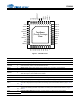
CS4244
3. CHARACTERISTICS AND SPECIFICATIONS
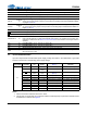
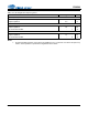
RECOMMENDED OPERATING CONDITIONS
GND = 0 V; all voltages with respect to ground. (Note 3)
Notes: 3. Device functional operation is guaranteed within these limits. Functionality is not guaranteed or
implied outside of these limits. Operation outside of these limits may adversely affect device reliability.
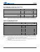
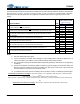
ABSOLUTE MAXIMUM RATINGS
GND = 0 V; all voltages with respect to ground.
WARNING:
OPERATION BEYOND THESE LIMITS MAY RESULT IN PERMANENT DAMAGE TO THE DEVICE.
Notes: 4. No external loads should be connected to the VDREG pin. Any connection of a load to this point may
result in errant operation or performance degradation in the device.
5. Any pin except supplies. Transient currents of up to ±100 mA on the analog input pins will not cause
SCR latch-up.
6. The maximum over/under voltage is limited by the input current.
Parameters Symbol Min Typ Max Units
DC Power Supply
Analog Core VA
3.135
4.75
3.3
5
3.465
5.25
V
V
Level Translator VL 1.71 - 5.25 V
Temperature
Ambient Operating Temperature - Power Applied Automotive
Commercial
T
A
-40
0
-
-
+85
+70
C
C
Junction Temperature T
J
-40 - +150 C
Parameters Symbol Min Max Units
DC Power Supply
Analog Core VA -0.3 5.5 V
Level Translator VL -0.3 5.5 V
VDREG Current (Note 4) I
VDREG
-10A
Inputs
Input Current (Note 5) I
in
-±10mA
Analog Input Voltage (Note 6) V
INA
- 0.3 VA + 0.4 V
Logic Level Input Voltage (Note 6) V
IND
-0.3 VL + 0.4 V
Temperature
Ambient Operating Temperature - Power Applied T
A
-55 +125 °C
Storage Temperature T
stg
-65 +150 °C