
User guide

DS900F1 36
CS4244
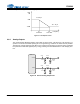
4.6.2.3 ADC HPF
The ADC path contains an optional HPF which can be enabled or disabled for all four ADCs via the “EN-
ABLE HPF” bit in the "ADC Control 1" register. The HPF should only be disabled when the DC component
of the input signal needs to be preserved in the digital output data. The HPF characteristics are given in
the ADC Digital Filter Characteristics table and plotted in Section 7. The Analog Input Characteristics ta-
bles on pages 11 and 12 specify the DC offset error when the HPF is enabled or disabled.
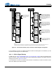
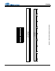
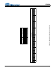
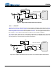
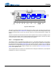
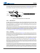
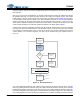
The following figure shows how the recommended single-ended to differential active input filter
(Figure 24) can be modified to allow for DC coupled inputs when the HPF is disabled. Note that the volt-
age swing should not exceed the ADC full-scale input specification.
VA
+
+
-
-
22 F
100 k
100 k
100 k
100 k
0.01 F22 F
470 pF
470 pF
C0G
C0G
634
634
634
91
91
2700 pF
C0G
AINx+
AINx-
ADC1-4
* Place close to AINx pins
*
Figure 24. Single-Ended to Differential Active Input Filter
VA
+
+
-
-
100 k
100 k
100 k
0.01 F 22 F
470 pF
470 pF
C0G
C0G
634
634
634
91
91
2700 pF
C0G
AINx+
AINx-
ADC1-4
* Place close to AINx pins
*
Figure 25. Single-Ended to Differential Active Input Filter - DC Coupled Input Signal (VA/2 Centered)