
User guide

DS900F1 35
CS4244
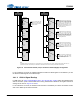
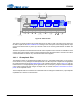
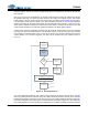
4.6.2 ADC Path
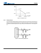
4.6.2.1 Analog Inputs
AINx+ and AINx- are line-level differential analog inputs. The analog input pins do not self-bias and must
be externally biased to VA/2 to avoid clipping of the input signal. The full-scale analog input levels are
scaled according to VA and can be found in the Analog Input Characteristics tables on pages 11 and 12.
The ADC output data is in two’s complement binary format. For inputs above positive full scale or below
negative full scale, the ADC will output 7FFFFFH or 800000H, respectively, and cause the ADC Overflow
bit in the Interrupt Notification 1 register to be set to a ‘1’.
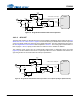
4.6.2.2 Active ADC Input Filter
The analog modulator samples the input at 6.144 MHz (internal MCLK = 12.288 MHz). The digital filter
will reject signals within the stopband of the filter. However, there is no rejection for input signals which
are multiples of the digital passband frequency (n
6.144 MHz), where n = 0,1,2,... Refer to Figure 24 for
a recommended analog input filter that will attenuate any noise energy at 6.144 MHz, in addition to pro-
viding the optimum source impedance for the modulators. The use of capacitors that have a large voltage
coefficient (such as general-purpose ceramics) must be avoided since these can degrade signal linearity.
I
2
C Contr ol
Data
Control Por t
Level Translator
VL
1.8 to 5.0 VDC
RST
INT
SDOUT1
LDO Analog Supply
2.5 V
VA
5.0 VDC
VD
2.5 VDC
Ser ial Audio Interface
SDOUT2
Serial Cl ock
In/Out
Master Clock In
Fram e Sync
Clock / LRCK
SDIN1SDIN2
AIN4 (±)
AIN3 (±)
AIN2 (±)
AIN1 (±)
Digital Filters
Multi-bit
ADC
AOUT1 (±)
AOUT2 (±)
AOUT3 (±)
AOUT4 (±)
Interpolation
Filter
Multi-bit
Modulators
Channel Vol ume ,
Mute, Invert ,
Noise Gate
DAC &
Analog
Filters
Master
Volume
Control
Figure 23. ADC Path