
User guide

DS900F1 31
CS4244
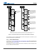
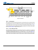
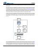
4.6 Internal Signal Path
The CS4244 device includes two paths in which audio data can be routed. The analog input path, shown in
yellow, allows up to four analog signals to be combined into a single TDM stream on the SDOUT1 pin or
output as stereo pairs on the SDOUT1 and SDOUT2 pins. The DAC1-4 path, highlighted in blue, converts
serial audio data to analog audio data.
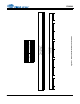
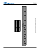
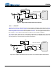
4.6.1 Routing the Serial Data within the Signal Paths
4.6.1.1 ADC Signal Routing
In TDM mode, the CS4244 is designed to load the first four slots of the TDM stream on the SDOUT1 pin
with the internal ADC data. Additionally, in order to minimize the number of SDOUT lines that must be run
to the system controller in a multiple IC application, the SDOUT data for up to 4 devices can be loaded
into a single TDM stream by side chaining the devices together, as shown in Figure 20. To enable the
sidechain feature, the “SDO CHAIN” bit in the "SP Control" register must be set.
I
2
C Control
Data
Control Port
Level Tr anslator
VL
1.8 to 5.0 VDC
RST
INT
SDOUT1
LDO Analog Supply
2.5 V
VA
5.0 VDC
VD
2.5 VDC
Serial Audio Inter face
SDOUT2
Serial Clock
In/Out
Master Clock In
Frame Sync
Clock / LRCK
SDIN1SDIN2
AIN4 (± )
AIN3 (± )
AIN2 (± )
AIN1 (± )
Digital Filters
Multi-bit
ADC
AOUT1 (±)
AOUT2 (±)
AOUT3 (±)
AOUT4 (±)
Interpol ation
Filter
Multi-bit
Modulator s
Channel Volum e ,
Mute, Invert ,
Noise Gate
DAC &
Analog
Filters
Master
Volume
Control
Figure 19. Audio Path Routing