
User guide

DS900F1 21
CS4244
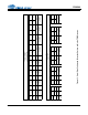
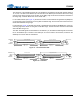
SWITCHING SPECIFICATIONS - CONTROL PORT
Test conditions (unless otherwise specified): Inputs: Logic 0 = GND = 0 V, Logic 1 = VL; SDA load capacitance equal to maxi-
mum value of C
b
specified below (Note 30).
Notes:
30. All specifications are valid for the signals at the pins of the CS4244 with the specified load capacitance.
31. 2 ms + (3000/MCLK). See Section 4.2.1.
32. Data must be held for sufficient time to bridge the transition time, t
f
, of SCL.
Parameters Symbol Min Max Unit
SCL Clock Frequency f
scl
- 550 kHz
RESET
Rising Edge to Start t
irs
(Note 31) -ns
Bus Free Time Between Transmissions t
buf
1.3 - µs
Start Condition Hold Time (prior to first clock pulse) t
hdst
0.6 - µs
Clock Low time t
low
1.3 - µs
Clock High Time t
high
0.6 - µs
Setup Time for Repeated Start Condition t
sust
0.6 - µs
SDA Input Hold Time from SCL Falling (Note 32) t
hddi
00.9µs
SDA Output Hold Time from SCL Falling t
hddo
0.2 0.9 µs
SDA Setup time to SCL Rising t
sud
100 - ns
Rise Time of SCL and SDA t
r
-300ns
Fall Time SCL and SDA t
f
-300ns
Setup Time for Stop Condition t
susp
0.6 - µs
SDA Bus Load Capacitance
C
b
-400pF
SDA Pull-Up Resistance
R
p
500 -
t
buf
t
hdst
t
hdst
t
low
t
r
t
f
t
hdd
t
high
t
sud
t
sust
t
susp
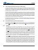
Stop Start
Start
Stop
Repeated
SDA
SCL
t
irs
RST
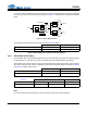
Figure 8. I²C Control Port Timing