
User guide

DS900F1 14
CS4244
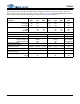
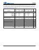
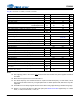
ADC DIGITAL FILTER CHARACTERISTICS
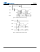
Test Conditions (unless otherwise specified): Device configured as shown in Section 2. on page 7. Input sine
wave: 1 kHz; VA_SEL = 0 for VA = 3.3 VDC, 1 for VA = 5.0 VDC.; Measurement Bandwidth is 20 Hz to 20 kHz
unless otherwise specified. See filter plots in Section 7. on page 59.
Note:
15. Response is clock-dependent and will scale with Fs.
16. The ADC group delay is measured from the time the analog inputs are sampled on the AINx pins to
the FS/LRCK transition (rising or falling) after the last bit of that (group of) sample(s) has been
transmitted on SDOUTx.
17. The amount of time from input of half-full-scale step function until the filter output settles to 0.1% of
full scale.
Parameter (Note 15) Min Typ Max Unit
Passband (Frequency Response) to -0.1 dB corner 0 - 0.4535 Fs
Passband Ripple -0.09 - 0.17 dB
Stopband 0.6 - - Fs
Stopband Attenuation 70 - - dB
Single-Speed Mode
ADC Group Delay (Note 16) - 9.5/Fs - s
High-Pass Filter Characteristics (48 kHz Fs)
Frequency Response -3.0 dB
-0.13 dB
-
-
2
11
-
-
Hz
Hz
Phase Deviation @ 20 Hz - 10 - Deg
Passband Ripple -0.09 - 0.17 dB
Filter Settling Time (Note 17) -
25000/Fs
0s
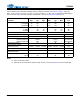
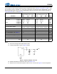
Double-Speed Mode
ADC Group Delay (Note 16) - 9.5/Fs - s
High-Pass Filter Characteristics (96 kHz Fs)
Frequency Response -3.0 dB
-0.13 dB
-
-
4
22
-
-
Hz
Hz
Phase Deviation @ 20 Hz - 10 - Deg
Passband Ripple -0.15 - 0.17 dB
Filter Settling Time (Note 17)
-
25000/Fs
0s