
User Manual


DS605F2 53
CS42428
6.12 Volume Control (addresses 0Fh, 10h, 11h, 12h, 13h, 14h, 15h, 16h)
6.12.1 VOLUME CONTROL (XX_VOL)
Default = 0
Function:
The Digital Volume Control registers allow independent control of the signal levels in 0.5 dB incre-
ments from 0 to -127 dB. Volume settings are decoded as shown in Table 13. The volume changes
are implemented as dictated by the Soft and Zero Cross bits (SZC[1:0]). All volume settings less than
-127 dB are equivalent to enabling the MUTE bit for the given channel.
6.13 Channel Invert (address 17h)
6.13.1 INVERT SIGNAL POLARITY (INV_XX)
Default = 0
0 - Disabled
1 - Enabled
Function:
When enabled, these bits will invert the signal polarity of their respective channels.
6.14 Mixing Control Pair 1 (Channels A1 & B1) (address 18h)
Mixing Control Pair 2 (Channels A2 & B2) (address 19h)
Mixing Control Pair 3 (Channels A3 & B3) (address 1Ah)
Mixing Control Pair 4 (Channels A4 & B4) (address 1Bh)
6.14.1 CHANNEL A VOLUME = CHANNEL B VOLUME (PX_A=B)
Default = 0
0 - Disabled
1 - Enabled
Function:
The AOUTAx and AOUTBx volume levels are independently controlled by the A and the B Channel
Volume Control registers when this function is disabled. The volume on both AOUTAx and AOUTBx
are determined by the A Channel Volume Control registers (per A-B pair), and the B Channel Volume
Control registers are ignored when this function is enabled.
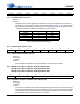
76543210
xx_VOL7 xx_VOL6 xx_VOL5 xx_VOL4 xx_VOL3 xx_VOL2 xx_VOL1 xx_VOL0
Binary Code Decimal Value Volume Setting
00000000 0 0 dB
00101000 40 -20 dB
01010000 80 -40 dB
01111000 120 -60 dB
10110100 180 -90 dB
Table 13. Example Digital Volume Settings
76543210
INV_B4 INV_A4 INV_B3 INV_A3 INV_B2 INV_A2 INV_B1 INV_A1
76543210
Px_A=B Reserved Reserved Px_ATAPI4 Px_ATAPI3 Px_ATAPI2 Px_ATAPI1 Px_ATAPI0