
Manual

10 DS603F2
CS42418
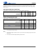
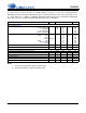
D/A DIGITAL FILTER CHARACTERISTICS
Notes:
9. Response is clock dependent and will scale with Fs. Note that the response plots (Figures 39 to 62) have
been normalized to Fs and can be de-normalized by multiplying the X-axis scale by Fs.
10. Single- and Double-Speed Mode Measurement Bandwidth is from stopband to 3 Fs.
Quad-Speed Mode Measurement Bandwidth is from stopband to 1.34 Fs.
11. De-emphasis is available only in Single-Speed Mode.
Parameter
Fast Roll-Off Slow Roll-Off
UnitMin Typ Max Min Typ Max
Combined Digital and On-chip Analog Filter Response - Single-Speed Mode - 48 kHz
Passband (Note 9) to -0.01 dB corner
to -3 dB corner
0
0
-
-
0.4535
0.4998
0
0
-
-
0.4166
0.4998
Fs
Fs
Frequency Response 10 Hz to 20 kHz
-0.01 - +0.01 -0.01 - +0.01 dB
StopBand
0.5465 - - 0.5834 - - Fs
StopBand Attenuation (Note 10)
90 - - 64 - - dB
Group Delay
- 12/Fs - - 6.5/Fs - s
Passband Group Delay Deviation 0 - 20 kHz
- - ±0.41/Fs - ±0.14/Fs s
De-emphasis Error (Note 11) Fs = 32 kHz
(Relative to 1 kHz) Fs = 44.1 kHz
Fs = 48 kHz
-
-
-
-
-
-
±0.23
±0.14
±0.09
-
-
-
-
-
-
±0.23
±0.14
±0.09
dB
dB
dB
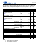
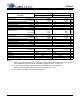
Combined Digital and On-chip Analog Filter Response - Double-Speed Mode - 96 kHz
Passband (Note 9) to -0.01 dB corner
to -3 dB corner
0
0
-
-
0.4166
0.4998
0
0
-
-
0.2083
0.4998
Fs
Fs
Frequency Response 10 Hz to 20 kHz
-0.01 - 0.01 -0.01 - 0.01 dB
StopBand
0.5834 - - 0.7917 - - Fs
StopBand Attenuation (Note 10)
80 - - 70 - - dB
Group Delay
- 4.6/Fs - - 3.9/Fs - s
Passband Group Delay Deviation 0 - 20 kHz
- - ±0.03/Fs - ±0.01/Fs s
Combined Digital and On-chip Analog Filter Response - Quad-Speed Mode - 192 kHz
Passband (Note 9) to -0.01 dB corner
to -3 dB corner
0
0
-
-
0.1046
0.4897
0
0
-
-
0.1042
0.4813
Fs
Fs
Frequency Response 10 Hz to 20 kHz
-0.01 - 0.01 -0.01 - 0.01 dB
StopBand
0.6355 - - 0.8683 - - Fs
StopBand Attenuation (Note 10)
90 - - 75 - - dB
Group Delay
- 4.7/Fs - - 4.2/Fs - s
Passband Group Delay Deviation 0 - 20 kHz
- - ±0.01/Fs - ±0.01/Fs s