
User Manual


DS602F2 57
CS42416
6.19 Interrupt Mask (address 21h)
Default = 00000000
Function:
The bits of this register serve as a mask for the interrupt sources found in the register “Interrupt Status
(address 20h) (Read Only)” on page 56. If a mask bit is set to 1, the error is unmasked, meaning that
its occurrence will affect the INT pin and the status register. If a mask bit is set to 0, the error is
masked, meaning that its occurrence will not affect the INT pin or the status register. The bit positions
align with the corresponding bits in the Interrupt Status register.
6.20 Interrupt Mode MSB (address 22h)
Interrupt Mode LSB (address 23h)
Default = 00000000
Function:
The two Interrupt Mode registers form a 2-bit code for each Interrupt Status register function. There
are three ways to set the INT pin active in accordance with the interrupt condition. In the Rising edge
active mode, the INT pin becomes active on the arrival of the interrupt condition. In the Falling edge
active mode, the INT pin becomes active on the removal of the interrupt condition. In Level active
mode, the INT interrupt pin becomes active during the interrupt condition. Be aware that the active
level (Active High or Low) only depends on the INT[1:0] bits located in the register “Interrupt Control
(address 1Eh)” on page 55.
00 - Rising edge active
01 - Falling edge active
10 - Level active
11 - Reserved
6.21 Mutec Pin Control (address 28h)
6.21.1 MUTEC POLARITY SELECT (MCPOLARITY)
Default = 0
0 - Active low
1 - Active high
Function:
Determines the polarity of the MUTEC pin.
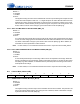
76543210
UNLOCKM Reserved Reserved Reserved Reserved Reserved OverFlowM Reserved
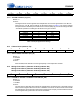
76543210
UNLOCK1 Reserved Reserved Reserved Reserved Reserved OF1 Reserved
UNLOCK0 Reserved Reserved Reserved Reserved Reserved OF0 Reserved
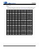
76543210
Reserved Reserved MCPolarity M_AOUTA1 M_AOUTB1 M_AOUTA2
M_AOUTB2
M_AOUTA3
M_AOUTB3
Reserved