
User Manual


DS899F1 14
CS4234
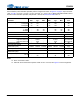
ADC DIGITAL FILTER CHARACTERISTICS
Test Conditions (unless otherwise specified): Device configured as shown in Section 2. on page 8. Input sine
wave: 1 kHz; VA_SEL = 0 for VA = 3.3 VDC, 1 for VA = 5.0 VDC.; T
A
= -40 to +105 C; Measurement Bandwidth is
20 Hz to 20 kHz unless otherwise specified. See filter plots in Section 7. on page 70.
Note:
15. Response is clock dependent and will scale with Fs.
16. The ADC group delay is measured from the time the analog inputs are sampled on the AINx pins to
the FS/LRCK rising transition after the last bit of that group of samples has been transmitted on
SDOUT1.
17. The amount of time from input of half-full-scale step function until the filter output settles to 0.1% of
full scale.
Parameter (Note 15) Min Typ Max Unit
Passband (Frequency Response) to -0.1 dB corner 0 - 0.4535 Fs
Passband Ripple -0.09 - 0.17 dB
Stopband 0.6 - - Fs
Stopband Attenuation 70 - - dB
Single-Speed Mode
ADC Group Delay (Note 16) - 9.5/Fs - s
High-Pass Filter Characteristics (48 kHz Fs)
Frequency Response -3.0 dB
-0.13 dB
-
-
2
11
-
-
Hz
Hz
Phase Deviation @ 20 Hz - 10 - Deg
Passband Ripple -0.09 - 0.17 dB
Filter Settling Time (Note 17)
-
25000/Fs
-s
Double-Speed Mode
ADC Group Delay (Note 16) - 9.5/Fs - s
High-Pass Filter Characteristics (96 kHz Fs)
Frequency Response -3.0 dB
-0.13 dB
-
-
4
22
-
-
Hz
Hz
Phase Deviation @ 20 Hz - 10 - Deg
Passband Ripple -0.15 - 0.17 dB
Filter Settling Time (Note 17)
-
25000/Fs
-s