
User Manual


CS4228A
8
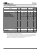
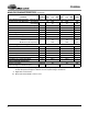
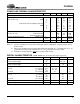
SWITCHING CHARACTERISTICS (Inputs: Logic 0 = 0V, Logic 1 = VL)
Notes: 14. See Cl1:0 register on page 22 for settings.
15. After powering up the CS4228A, RST
should be held low for 1 ms after the power supplies and clocks
are settled.
16. Scales with sample rate Fs. 50 ns valid at 48 kHz, more time at slower Fs and less time at faster Fs.
17. See DCK1:0 register on page 25 for settings.
Parameter Symbol Min Typ Max Units
Audio ADC's and DAC's Sample Rate BRM
HRM
Fs 30
60
-
-
50
100
kHz
kHz
MCLK Frequency (Note 14) 3.84 - 25.6 MHz
MCLK Duty Cycle BRM
MCLK =128, 384 Fs
MCLK = 256, 512 Fs
HRM
MCLK = 64, 192 Fs
MCLK = 128, 256 Fs
40
40
40
40
50
50
50
50
60
60
60
60
%
%
%
%
RST
Low Time (Note 15)
1--ms
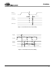
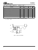
SCLK Falling Edge to SDOUT Output Valid (Note 16) t
dpd
-50ns
LRCK Edge to MSB Valid t
lrpd
-20ns
SDIN Setup Time Before SCLK Rising Edge t
ds
-10ns
SDIN Hold Time After SCLK Rising Edge t
dh
-30ns
SCLK Period BRM (Note 17) t
sck
--ns
SCLK Period HRM (Note 17) t
sck
--ns
Master Mode
SCLK Falling to LRCK Edge t
mslr
+10 - ns
SCLK Duty Cycle 50 - %
Slave Mode
SCLK High Time t
sckh
50 - - ns
SCLK Low Time t
sckl
50 - - ns
SCLK rising to LRCK Edge t
lrckd
25 - - ns
LRCK Edge to SCLK Rising t
lrcks
25 - - ns
1
128()Fs
----------------------
1
64()Fs
------------------