
User Manual


CS4228A
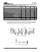
16
channels of DAC data is input on SDIN1 and the
stereo ADC data is output on SDOUT. Table 1 out-
lines the serial port input to DAC channel
allocations.
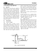
3.6.2 Serial Audio Interface Formats
The digital audio port supports 6 formats, shown in
Figure 10, 11, 12 and 13. These formats are select-
ed using the DDF2:0 bits in the Serial Port Mode
register.
In One Line Data Mode, all 6 DAC channels are in-
put on SDIN1. One Line Data Mode is only avail-
able in BRM. See Figure 13 for channel
allocations.
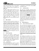
DAC Inputs
SDIN1 left channel
right channel
single line
DAC #1
DAC #2
All 6 DAC channels (BRM)
SDIN2 left channel
right channel
DAC #3
DAC #4
SDIN3 left channel
right channel
DAC #5
DAC #6
Table 1. Serial Audio Port Input Channel Allocations
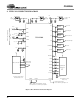
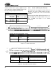
LRCK
SCLK
Left Channel
Right Channel
6543210987
15 14 13 12 11 10
6543210987
15 14 13 12 11 10
SDINx
Figure 10. I
2
S Serial Audio Formats
I2S Mode, Data Valid on Rising Edge of SCLK
Bits/Sample SCLK Rate(s) Notes
16 32, 48, 64, 128 Fs
32, 64 Fs
BRM, 48 Fs available in slave mode only
HRM
18 to 24 48, 64, 128 Fs
64 Fs
BRM, 48 Fs available in slave mode only
HRM
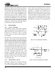
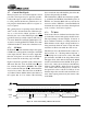
LRCK
SCLK
Left Channel
Right Channel
SDIN1/2/3
SDOUT
+3 +2 +1
LSB
+5 +4
MSB
-1 -2 -3 -4 -5
+3 +2 +1
LSB
+5 +4
MSB
-1 -2 -3 -4
Figure 11. Left Justified Serial Audio Formats
Left Justified Mode, Data Valid on Rising Edge of SCLK
Bits/Sample SCLK Rate(s) Notes
16 32, 48, 64, 128 Fs
32, 64 Fs
BRM, 48 Fs available in slave mode only
HRM
18 to 24 48, 64, 128 Fs
64 Fs
BRM, 48 Fs available in slave mode only
HRM