
Manual
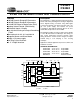


CS4223 CS4224
DS290F1 3
5.5.3 Serial Data Output Format (DOF).................................................................................. 17
5.5.4 Serial Data Input Format (DIF) ...................................................................................... 17
5.6 Converter Status Report (Read Only) (address 06h) ....................................................... 18
5.6.1 Left and Right Channel Acceptance Bit (ACCR-ACCL) ................................................ 18
5.6.2 Left and Right Channel ADC Output Level (LVR and LVL) ........................................... 18
5.7 Master Clock Control (address 07h)................................................................................. 18
5.7.1 Master Clock Control (MCK).......................................................................................... 18
6. PIN DESCRIPTIONS — CS4223 ............................................................................................ 19
7. PIN DESCRIPTIONS — CS4224 ............................................................................................ 21
8. APPLICATIONS ..................................................................................................................... 23
8.1 Overview .......................................................................................................................... 23
8.2 Grounding and Power Supply Decoupling ....................................................................... 23
8.3 High Pass Filter ...............................................................................................................23
8.4 Analog Outputs ................................................................................................................23
8.5 Master vs. Slave Mode .................................................................................................... 23
8.6 De-emphasis ................................................................................................................... 23
8.7 Power-up / Reset / Power Down Calibration ................................................................... 23
8.8 Control Port Interface (CS4224 only) .............................................................................. 24
8.8.1 SPI Mode ............................................................................................................ 24
8.8.2 I
2
C Mode ............................................................................................................. 24
8.9 Memory Address Pointer (MAP)....................................................................................... 25
8.9.1 Auto-Increment Control (INCR) ..................................................................................... 25
8.9.2 Register Pointer (MAP).................................................................................................. 25
9. ADC/DAC FILTER RESPONSE .............................................................................................. 29
10. PARAMETER DEFINITIONS................................................................................................. 30
11. PACKAGE DIMENSIONS ..................................................................................................... 31
LIST OF FIGURES
Figure 1. Serial Audio Port Data I/O Timing ............................................................................ 8
Figure 2. SPI Control Port Timing............................................................................................ 9
Figure 3. I
2
C Control Port Timing .......................................................................................... 10
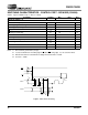
Figure 4. CS4223 Recommended Connection Diagram ....................................................... 11
Figure 5. CS4224 Recommended Connection Diagram ....................................................... 12
Figure 6. Control Port Timing, SPI mode............................................................................... 25
Figure 7. Control Port Timing, I
2
C mode ............................................................................... 25
Figure 8. Serial Audio Format 0 (I2S).................................................................................... 26
Figure 9. Serial Audio Format 1............................................................................................. 26
Figure 10. Serial Audio Format 2............................................................................................. 26
Figure 11. Serial Audio Format 3............................................................................................. 27
Figure 12. Optional Input Buffer .............................................................................................. 27
Figure 13. Single-ended Input Application............................................................................... 27
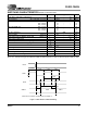
Figure 14. 2- and 3-Pole Butterworth Filters............................................................................ 28
Figure 15. De-emphasis Curve................................................................................................ 28
Figure 16. Hybrid Analog/Digital Attenuation........................................................................... 28
Figure 17. ADC Filter Response.............................................................................................. 29
Figure 18. ADC Passband Ripple............................................................................................ 29
Figure 19. ADC Transition Band.............................................................................................. 29
Figure 20. DAC Filter Response.............................................................................................. 29
Figure 21. DAC Passband Ripple............................................................................................ 29
Figure 22. DAC Transition Band.............................................................................................. 29