
Manual


CS4223 CS4224
12 DS290F1
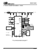
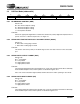
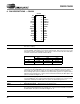
2. TYPICAL CONNECTION DIAGRAM — CS4223
AINL+
AINL-
1µF
+ 0.1 µF
2
Ω
0.1 µF + 1µF
+5V
Supply
21 6
VA VD
Ferrite Bead
2.2 nF
150
Ω
150
Ω
AINR+
AINR-
2.2 nF
150
Ω
150
Ω
20
19
17
16
22
7
AGND
DGND
10
11
Mode Selection
DIF1
DIF0
5
4
Audio
DSP
SCLK
LRCK
9
SDIN
8
SDOUT
R
s
R
s
CS4223
27
RST
R=500
Ω
NC
1
NC
14
NC
15
NC
28
R
s
R
s
s
0.1 µF + 1µF
13
VL
+2.7 - 5V
47 k
Ω
*
* Required for
Master Mode only
Digital Audio
Source
18
25
26
AOUTL+
AOUTL-
24
23
Analog Filter
AOUTR+
AOUTR-
12
DEM0
DEM1
XTI
XTO
2
3
External
Clock Input
40 pF
40 pF
Eliminate the crystal
and capacitors when
using an external
clock input
Analog Filter
Figure 4. CS4223 Recommended Connection Diagram
(Also see Recommended Layout Diagram)