
Manual

CS4220 CS4221
DS284PP3 9
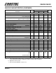
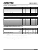
SWITCHING CHARACTERISTICS - CONTROL PORT - I
2
C MODE (CS4221)
(T
A
= 25° C; VA, VD = 4.75 V - 5.25 V; Inputs: Logic 0 = DGND, Logic 1 = VD; C
L
= 30 pF)
Notes: 15. Not tested but guaranteed by design.
16. Data must be held for sufficient time to bridge the 300 ns transition time of SCL.
Parameter Symbol Min Max Unit
I
2
C
®
Mode (SPI/I2C = 1)
SCL Clock Frequency f
scl
-100kHz
RST
rising edge to Start (Note 15)
t
irs
50 - µs
Bus Free Time between transmissions t
buf
4.7 - µs
Start Condition Hold Time (prior to first clock pulse) t
hdst
4.0 - µs
Clock Low Time t
low
4.7 - µs
Clock High Time t
high
4.0 - µs
Setup time for repeated Start Condition t
sust
4.7 - µs
SDA hold time for SCL falling (Note 16) t
hdd
0-µs
SDA setup time to SCL rising t
sud
250 - ns
Rise time of SCL t
rc
-25ns
Fall time of SCL t
fc
-25ns
Rise time of SDA t
rd
-1µs
Fall time of SDA t
fd
-300ns
Setup time for Stop Condition t
susp
4.7 - µs
t
buf
t
hdst
t
hdst
t
low
t
rc
t
fc
t
hdd
t
high
t
sud
t
sust
t
susp
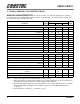
Stop Start
Start
Stop
Repeated
SDA
SCL
t
irs
RST
t
rd
t
fd
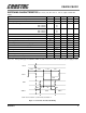
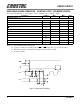
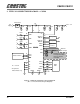
Figure 3. I
2
C Control Port Timing