
Manual
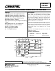

CS4220 CS4221
4 DS284PP3
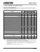
1. CHARACTERISTICS AND SPECIFICATIONS
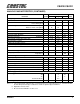
ANALOG CHARACTERISTICS (T
A
= 25° C; VA, VD = +5 V; Full Scale Input Sine wave, 997 Hz;
Fs = 48 kHz; Measurement Bandwidth is 20 Hz to 20 kHz; Local components as shown in Figures 4 and 5; SPI
mode, Format 0, unless otherwise specified.)
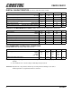
Notes: 1. Referenced to typical full-scale differential input voltage (2 Vrms).
2. Filter characteristics scale with output sample rate. For output sample rates, Fs, other than 48 kHz, the
0.01 dB passband edge is 0.4535x Fs and the stopband edge is 0.625x Fs.
3. The analog modulator samples the input at 6.144 MHz for an Fs equal to 48 kHz. There is no rejection
of input signals which are multiples of the sampling frequency (n x 6.144 MHz ±21.8 kHz where
n = 0,1,2,3...).
4. Group delay for Fs = 48 kHz, t
gd
= 15/48 kHz = 312 µs.
Parameter Symbol
CS4220/1 - KS
UnitMin Typ Max
Analog Input Characteristics
ADC Resolution - - 24 Bits
Total Harmonic Distortion THD - 0.003 - %
Dynamic Range A-weighted
unweighted
95
92
100
97
-
-
dB
Total Harmonic Distortion + Noise (Note 1) THD+N - -92 -87 dB
Interchannel Isolation (1 kHz) - 90 - dB
Interchannel Gain Mismatch - - 0.1 dB
Offset Error with High Pass Filter - - 0 LSB
Full Scale Input Voltage (Differential) 1.9 2.0 2.1 Vrms
Gain Drift - 100 - ppm/°C
Input Resistance 10 - - kΩ
Input Capacitance - - 15 pF
Common Mode Input Voltage - 2.3 - V
A/D Decimation Filter Characteristics
Passband (Note 2) 0 - 21.8 kHz
Passband Ripple - - ±0.01 dB
Stopband (Note 2) 30 - 6114 kHz
Stopband Attenuation (Note 3) 80 - - dB
Group Delay (Fs = Output Sample Rate)
(Note 4)
t
gd
-15/Fs- s
Group Delay Variation vs. Frequency ∆t
gd
--0µs
High Pass Filter Characteristics
Frequency Response -3 dB (Note 2)
-0.1 dB
-
-
3.7
20
-
-
Hz
Phase Deviation @ 20 Hz (Note 2) - 10 - Degree
Passband Ripple - - 0 dB