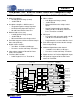
CS4207 Low-power, 4-in / 6-out HD Audio Codec with Headphone Amp DIGITAL to ANALOG FEATURES ANALOG to DIGITAL FEATURES DAC1 (Headphone) ADC1 & ADC2 – – 101 dB Dynamic Range (A-wtd) -89 dB THD+N – – – Headphone Amplifier - GND Centered – – – Integrated Negative-voltage Regulator No DC-blocking Capacitor Required 50 mW Power/Channel into 16 – DAC2 & DAC3 (Line Outs) – – – MIC Inputs 110 dB Dynamic Range (A-wtd) -94 dB THD+N Differential Balanced or Single-ended – Each DAC Support
CS4207 Digital Audio Interface Receiver General Description Complete EIAJ CP1201, IEC 60958, S/PDIF The CS4207 is a highly integrated multi-channel lowpower HD Audio Codec featuring 192 kHz DACs, 96 kHz ADCs, 192 kHz S/PDIF Transmitters and Receiver, Microphone pre-amp and bias voltage, and a ground centered Headphone driver. Based on multi-bit, delta-sigma modulation, it allows infinite sample rate adjustment between 32 kHz and 192 kHz.
CS4207 TABLE OF CONTENTS 1. PIN DESCRIPTIONS .............................................................................................................................. 8 1.1 CS4207 48-pin QFN Pinout: ............................................................................................................ 8 1.2 Digital I/O Pin Characteristics ........................................................................................................ 10 2. TYPICAL CONNECTION DIAGRAMS ......................
CS4207 6.3.13 Implementation Identification ............................................................................................... 44 6.3.14 Function Reset .................................................................................................................... 44 6.4 DAC1, DAC2, DAC3 Output Converter Widgets (Node ID = 02h, 03h, 04h) ................................. 45 6.4.1 Audio Widget Capabilities ......................................................................................
CS4207 6.8.7 Pin Widget Control ................................................................................................................ 81 6.8.8 Unsolicited Response Control ............................................................................................... 82 6.8.9 Pin Sense .............................................................................................................................. 83 6.8.10 Configuration Default .......................................................
CS4207 6.13.7 Pin Sense .......................................................................................................................... 118 6.13.8 Configuration Default ......................................................................................................... 119 6.14 S/PDIF Transmitter 1, S/PDIF Transmitter 2 Output Pin Widgets (Node ID = 10h, 15h) ........... 120 6.14.1 Audio Widget Capabilities .....................................................................................
CS4207 LIST OF FIGURES Figure 1.Typical Connection Diagram - Desktop System ......................................................................... 11 Figure 2.Typical Connection Diagram - Portable System ......................................................................... 12 Figure 3.Output Test Load, Headphone Out ............................................................................................. 18 Figure 4.Output Test Load, Line Out ......................................................
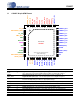
CS4207 1. PIN DESCRIPTIONS SPDIF_IN VA_HP FLYP VHP_FILT+ FLYC FLYN VHP_FILT- HPOUT_R HPREF HPOUT_L LINEOUT_R1- CS4207 48-pin QFN Pinout: SPDIF_OUT1 1.
CS4207 Pin Name QFN Pin Description RESET# 11 Reset (Input) - The device enters a low power mode when this pin is driven low. GPIO1/ DMIC_SDA2/ SPDIF_OUT2 12 General Purpose I/O (Input/Output) - General purpose input or output line, or Digital Mic Data Input (Input) - The second data input line from a digital microphone, or S/PDIF Output (Output) - Output from internal S/PDIF Transmitter. SENSE_A 13 Jack Sense Pin (Input/Output) - Jack sense detect.
CS4207 1.2 Digital I/O Pin Characteristics Input and output levels and associated power supply voltage are shown in the table below. Logic levels should not exceed the corresponding power supply voltage. Power Supply VL_HD VA VL_IF Pin Name SW/(HW) RESET# SDO BITCLK SDI (Note 1) SYNC SENSE_A GPIO1/ DMIC_SDA2 GPIO2 GPIO3 SPDIF_IN SPDIF_OUT GPIO0/ DMIC_SDA1 DMIC_SCL I/O Driver Receiver Input Input Input Input/Output Input Input 1.5 V - 3.3 V - 1.5 V - 3.3 V 1.5 V - 3.3 V 1.5 V - 3.3 V 1.5 V - 3.
CS4207 2. TYPICAL CONNECTION DIAGRAMS +5.0 V +1.8 V 0.1 µF 0.1 µF VD VA +5.0 V 0.1 µF + VA_REF 10 µF HPOUT_L VBIAS VA_HP +5.0 V CS4207 VHP_FILT+ Left Headphone 33 0.1 µF HPREF Headphone Ground HPOUT_R Right Headphone 33 0.1 µF VHP_FILT0.
CS4207 +3.3 V +1.8 V 0.1 µF 0.1 µF VD VA +3.3 V 0.1 µF + VA_REF 10 µF HPOUT_L VBIAS VA_HP +3.3 V CS4207 VHP_FILT+ Left Headphone 33 0.1 µF HPREF Headphone Ground HPOUT_R Right Headphone 33 0.1 µF VHP_FILT0.1 µF **10 µF **10 µF LINEOUT_L1+ LINEOUT_L1FLYP ** 2.2 µF FLYC LINEOUT_R1+ FLYN LINEOUT_R1- ** 2.2 µF * *Use low ESR ceramic capacitors.
CS4207 3. CHARACTERISTICS AND SPECIFICATIONS RECOMMENDED OPERATING CONDITIONS (AGND=DGND=0 V, all voltages with respect to ground.) Parameters DC Power Supply (Note 1) Analog Core DAC Reference Headphone Amplifier Digital Core HD Audio Bus Interface GPIO, S/PDIF and Digital Mic Interface Ambient Temperature Symbol Min Max Units VA VA_REF VA_HP VD VL_HD VL_IF 2.97 2.97 2.97 1.42 1.42 2.97 -40 -40 5.25 5.25 5.25 1.89 3.47 3.
CS4207 ANALOG INPUT CHARACTERISTICS (COMMERCIAL - CNZ) (Test Conditions (unless otherwise specified): Input sine wave (relative to digital full-scale): 1 kHz through passive input filter; VA_HP = VA; VL_HD = VL_IF = 3.3; VD = 1.8 V; TA = +25C; Measurement Bandwidth is 10 Hz to 20 kHz unless otherwise specified. Sample Frequency = 48 kHz) VA, VA_REF = 5.0 V VA, VA_REF = 3.
CS4207 ANALOG INPUT CHARACTERISTICS (AUTOMOTIVE - DNZ) (Test Conditions (unless otherwise specified): Input sine wave (relative to digital full-scale): 1 kHz through passive input filter; VA_HP = VA; VL_HD = VL_IF = 3.3; VD = 1.8 V; TA = -40 to +85C; Measurement Bandwidth is 10 Hz to 20 kHz unless otherwise specified. Sample Frequency = 48 kHz) VA, VA_REF = 5.0 V VA, VA_REF = 3.
CS4207 ADC DIGITAL FILTER CHARACTERISTICS Parameter (Note 6) Passband (Frequency Response) Passband Ripple Stopband Stopband Attenuation Total Group Delay High-Pass Filter Characteristics (48 kHz Fs) Frequency Response -3.0 dB -0.13 dB Phase Deviation @ 20 Hz Passband Ripple to -0.1 dB corner Filter Settling Time Min 0 -0.09 0.6 70 - Typ 7.6/Fs Max .4535 0.17 - Unit Fs dB Fs dB s - 3.6 24.2 - Hz Hz - 10 - Deg - - 0.17 dB - 105/Fs 0 s 6.
CS4207 ANALOG OUTPUT CHARACTERISTICS (COMMERCIAL - CNZ) (Test conditions (unless otherwise specified): Input test signal is a full-scale 997 Hz sine wave; VD = 1.8 V; VL_HD = VL_IF = 3.3V; TA = +25C; Measurement bandwidth is 10 Hz to 20 kHz; test load RL = 10 k CL = 10 pF for the line output and test load RL = 16 CL = 10 pF for the headphone output (see Figure 3); DAC Gain = 0 dB).
CS4207 VA, VA_REF = 5.0 V (Differential/Single-ended) Min Typ Max Parameter (Note 4) VA, VA_REF = 3.
CS4207 ANALOG OUTPUT CHARACTERISTICS (AUTOMOTIVE - DNZ) (Test conditions (unless otherwise specified): Input test signal is a full-scale 997 Hz sine wave; VD = 1.8 V; VL_HD = VL_IF = 3.3V; TA = -40 to +85C; Measurement bandwidth is 10 Hz to 20 kHz; test load RL = 10 k CL = 10 pF for the line output and test load RL = 16 CL = 10 pF for the headphone output (see Figure 5); DAC Gain = 0 dB).
CS4207 VA, VA_REF = 5.0 V (Differential/Single-ended) Min Typ Max Parameter (Note 4) VA, VA_REF = 3.
CS4207 COMBINED DAC INTERPOLATION & ON-CHIP ANALOG FILTER RESPONSE Parameter Min Frequency Response 10 Hz to 20 kHz Passband -0.01 to -0.01 dB corner to -3 dB corner 0 0 StopBand - StopBand Attenuation (Note 9) - Total Group Delay - Typ 26256 102 0.196 Max +0.01 21792 23952 - Unit dB Hz Hz Hz dB ms 9. Measurement Bandwidth is from Stopband to 100 kHz. DC ELECTRICAL CHARACTERISTICS (AGND = 0 V; all voltages with respect to ground.) Parameters Min Typ Max Units - 0.
CS4207 DIGITAL MICROPHONE INTERFACE CHARACTERISTICS Test conditions: Inputs: Logic 0 = GND = 0 V, Logic 1 = VL_IF; TA = +25 C; CLOAD = 30 pF. Parameters Symbol Min Typ Max Units DMIC_SCL Period (FsADC >= 44.1 kHz) (Note 12) tP - 8 • T_cyc - ns DMIC_SCL Period (FsADC <= 32.
CS4207 DIGITAL INTERFACE SPECIFICATIONS & CHARACTERISTICS Parameters (Note 14) Input Leakage Current Input Pin Capacitance VL_HD = 1.5 V High-Level Input Voltage Low-Level Input Voltage High-Level Output Voltage (IOUT = -500 A) Symbol Iin Cin Min - Max ±10 7.5 Units A pF VIH 0.60•VL_HD - V VIL - 0.40•VL_HD V VOH 0.90•VL_HD - V Low-Level Output Voltage (IOUT = 1500 A) VOL - 0.10•VL_HD V VIH 0.65•VL_HD - V VL_HD = 3.3 V High-Level Input Voltage Low-Level Input Voltage VIL - 0.
CS4207 POWER CONSUMPTION (This table represents the power consumption for individual circuit blocks within the codec) (See (Note 15)) Typical Current (mA) iVA Individual Block Operation Codec D3 State- unsolicited 1 response capable (Note 16) ADC1 or ADC2 with PGA oper- 2 ation and Pseudo-Diff Inputs DAC1 with Headphone/Line 3 Out (Note 17) DAC2 or DAC3 with Differen- 4 tial Line Out (Note 18) S/PDIF transmitter with SRC 5 function S/PDIF receiver with SRC 6 function VA/ VA_HP 3.3 5.0 3.3 5.0 3.
CS4207 4. CODEC RESET AND INITIALIZATION 4.1 Link Reset A Link Reset is a system controller generated assertion of the HD Audio Bus RESET# signal. A Link reset will cause some of the HD Audio bus interface logic to be initialized. Following a Link Reset, the CS4207 will perform the Codec Initialization request sequence. Many of the codec settings will remain unchanged following a Link Reset. See “Register Settings Across Reset Conditions” section on page 29 for more details.
CS4207 If RESET# is asserted low, and BITCLK and SYNC are not running at the time (defined as link low power state), the codec will signal the power state change request and initialization request asynchronously by asserting SDI high continuously until it detects the de-assertion of RESET#. It will then asynchronously drive SDI low with the de-assertion of the RESET#. With the RESET# signal high, the codec will reestablish the connection with the controller by performing a “Codec Initialization request”.
CS4207 . DAC Output Converter Widget LineOut Output Pin Widget D0/D3 Power States D0/D3 Power States ADC Input Converter Widget Line In Input Pin Widget D0/D3 Power States D0/D3 Power States HD_Audio Bus Output Path Output Converter Widget D0 Output Pin Widget D0 • Pin widget outputs a muted audio signal, supports presence detect if enabled and transitions to D3.
CS4207 4.6 Power State Settings Reset (PS-SettingsReset) PS-SettingsReset is reported as set to one ‘1’b when, during any low power state transition the settings that were changed from the defaults (either through software or hardware) have been reset back to their default state. When these settings have not been reset, this is reported as ‘0’b. The conditions that may reset settings to their defaults are: 1.
CS4207 4.7 Register Settings Across Resets The CS4207 will perform a complete Power On Reset (POR) initialization if the voltage is cycled from off to on from the VD pin of the device. All registers will be initialized to the default state. For device behavior due to other system reset conditions or power state transitions events, see the table below.
CS4207 Setting Action with Link Reset Action with “Double” Function Group reset Action with “Single” Function Group reset Action across D0/D3 state transitions or link BITCLK stopped Pin Sense; Presence Detect Bit only. (verb ID = F09/709) Update to reflect proper state and save any Unsolicited Response that has not been sent and send it after first verb is received. Update to reflect proper state and issue an Unsolicited Response if enabled.
CS4207 5. PRESENCE DETECTION 5.1 Jack Detection Circuit The jack detection circuit provides attachment for to up to four pluggable jacks as described in the High Definition Audio Specification. Each jack has an isolated switch (normally open), as shown in Figure 9, which closes when a plug is inserted into that jack. A “power of two” parallel resistor network is connected to the SENSE_A pin as shown.
CS4207 If the codec has detected that the link is entering a Link Reset state (see description below), all Unsolicited Response requests will be buffered. Once the link is in the Link Reset state, with RESET# asserted low, the codec will request a power state change and initialization request.
CS4207 6. HD AUDIO CODEC SUPPORTED VERBS AND RESPONSES 6.
CS4207 6.1.1 Node ID Summary Node ID Description Reference Section 00h Root Node Section 6.2 on page 36 01h Audio Function Group Section 6.3 on page 37 02h DAC1 Output Converter Widget Section 6.4 on page 45 03h DAC2 Output Converter Widget Section 6.4 on page 45 04h DAC3 Output Converter Widget Section 6.4 on page 45 05h ADC1 Input Converter Widget Section 6.5 on page 53 06h ADC2 Input Converter Widget Section 6.5 on page 53 07h S/PDIF Receiver Input Converter Widget Section 6.
CS4207 6.1.2 Pin Configuration Register Defaults The Configuration Default Register is required for each Pin Widget. It is used by software as an aid in determining the configuration of jacks and devices attached to the codec. At the time the codec is first powered on, this register is internally loaded with default values, see Table 3, indicating the typical system use of this particular pin/jack.
CS4207 6.2 6.2.1 Root Node (Node ID = 00h) Vendor and Device ID Get Parameter Command Format: Bits [31:28] Bits [27:20] Bits [19:8] Bits [7:0] CAd = X Node ID = 00h Verb ID = F00h Parameter ID = 00h Type Default Description Response Format: Bits 6.2.
CS4207 6.3 Audio Function Group (Node ID = 01h) 6.3.1 Subordinate Node Count Get Parameter Command Format: Bits [31:28] Bits [27:20] Bits [19:8] Bits [7:0] CAd = X Node ID = 01h Verb ID = F00h Parameter ID = 04h Bits Type Default Description 31:24 Read Only 00h Reserved 23:16 Read Only 02h Starting Node Number (SNN): 2 Response Format: 6.3.
CS4207 6.3.4 Supported PCM Size, Rates Get Parameter Command Format: Bits [31:28] Bits [27:20] Bits [19:8] Bits [7:0] CAd = X Node ID = 01h Verb ID = F00h Parameter ID = 0Ah Type Default Description 31:21 Read Only 00000000000b 20 Read Only 1b 32-Bit (32B): 32-bit audio format is supported. Response Format: Bits 38 Reserved 19 Read Only 1b 24-Bit (24B): 24-bit audio format is supported. 18 Read Only 1b 20-Bit (20B): 20-bit audio format is supported.
CS4207 6.3.5 Supported Stream Formats Get Parameter Command Format: Bits [31:28] Bits [27:20] Bits [19:8] Bits [7:0] CAd = X Node ID = 01h Verb ID = F00h Parameter ID = 0Bh Type Default Description Response Format: Bits 6.3.6 31:3 Read Only 0 Reserved 2 Read Only 0b AC-3 (AC3): AC-3™ data is not supported. 1 Read Only 0b Float32 (FLT32): Float32 formatted data is not supported on this widget.
CS4207 • 6.3.7 Reporting of ClkStopOk when stopping of the clock would be permitted. The CLKSTOP is a static capability with ClkStopOk a dynamic reporting. The setting the capability CLKSTOP to one (1) and not allowing the clock to stop by not reporting ClkStopOk is not permissible. Unless there is a condition or dependency that the host software cannot be made aware of, that would prohibit stopping the clock, the ClkStopOk shall be reported as set (1).
CS4207 6.3.
CS4207 state for the Audio Function Group node will force all other nodes with power state control to the D3 state. If the Power State field for this node is set to D0, then the individual power state for each converter will be uniquely controlled via the corresponding node Power State field. PS-Act is a Power State field which indicates the actual power state of the referenced node.
CS4207 6.3.10 GPIO Enable Mask Get Parameter Command Format: Bits [31:28] Bits [27:20] Bits [19:8] Bits [7:0] CAd = X Node ID = 01h Verb ID = F16h Payload = 00h Set Parameter Command Format: Bits [31:28] Bits [27:20] Bits [19:8] Bits [7:0] CAd = X Node ID = 01h Verb ID = 716h Payload = xxh Response Format: Bits Type Default 31:8 Read Only 000000h 7:4 Read Only 0h GPIO[7:4] Enable Mask: Not Supported.
CS4207 Response Format: Bits Type Default 31:8 Read Only 000000h 7:4 Read Only 0h GPIO[7:4] Sticky Mask: Not Supported. 0h GPIO[3:0] Sticky Mask: Defines GPIO Input Type (0 = Non-Sticky, 1 = Sticky) when a GPIO pin is configured as an input. GPIO inputs configured as Sticky are cleared by writing a 0 to the corresponding bit of the GPIO Data Control The default value for these bits (0h) is all pins Non-Sticky. Non implemented GPIO pins always return 0’s.
CS4207 6.4 DAC1, DAC2, DAC3 Output Converter Widgets (Node ID = 02h, 03h, 04h) 6.4.
CS4207 6.4.2 Supported PCM Size, Rates Get Parameter Command Format: Bits [31:28] Bits [27:20] Bits [19:8] Bits [7:0] CAd = X DAC1 Node ID=02h DAC2 Node ID=03h DAC3 Node ID=04h Verb ID = F00h Parameter ID = 0Ah Response Format: 6.4.3 Bits Type Default 31:21 Read Only 00000000000b Description Reserved 20 Read Only 1b 32-Bit (32B): 32-bit audio format is supported. 19 Read Only 1b 24-Bit (24B): 24-bit audio format is supported.
CS4207 Response Format: Bits 6.4.4 Type Default Description 31:3 Read Only 0 Reserved 2 Read Only 0b AC-3 (AC3): AC-3 data is not supported. 1 Read Only 0b Float32 (FLT32): Float32 formatted data is not supported on this widget. 0 Read Only 1b Pulse Code Modulation (PCM): PCM formatted data is supported on this widget.
CS4207 6.4.
CS4207 6.4.7 Converter Stream, Channel Get Parameter Command Format: Bits [31:28] Bits [27:20] Bits [19:8] Bits [7:0] CAd = X DAC1 Node ID=02h DAC2 Node ID=03h DAC3 Node ID=04h Verb ID = F06h Payload = 00h Set Parameter Command Format: Bits [31:28] Bits [27:20] Bits [19:8] Bits [7:0] CAd = X DAC1 Node ID=02h DAC2 Node ID=03h DAC3 Node ID=04h Verb ID = 706h Payload = xxh Response Format: Bits Type Default 31:8 Read Only 000000h 7:4 Read/Write 3:0 6.4.
CS4207 Response Format: Bits [15:0] must be programmed with the same value programmed into the Stream Descriptor, so that the data format being transmitted on the link matches what is expected by the consumer of the data. If the TYPE is set to Non-PCM, the controller pushes data over the link and is not concerned with formatting. The base rate, data type, and number of Words (MULT) to send each valid frame are specified to control the rate at which the non-PCM data is sent.
CS4207 6.4.9 Amplifier Gain/Mute Get Parameter Command Format: Bits [31:28] Bits [27:20] Bits [19:16] Bits [15:0] CAd = X DAC1 Node ID=02h DAC2 Node ID=03h DAC3 Node ID=04h Verb ID = Bh Payload = xxxxh Bits [19:16] = ‘Bh’, where bits [15:0] are defined below: Bits [15:0] Value Description 15 1b Get Output/Input (GOI): This bit controls whether the request is for the input amplifier or the output amplifier. When ‘1’, the output amplifier is being requested.
CS4207 Bits [19:16] = ‘3h’, where bits [15:0] are defined below: Bits Type Default Description 15 Write Only xb Set Output Amplifier (SOA): Determines if the value programmed refers to the output amplifier. Set to a 1 for the value to be accepted. 0b Set Input Amplifier (SIA): Determines if the value programmed refers to the input amplifier. This bit should always be ‘0’ since an input amplifier is not present on this widget. xb Set Left Amplifier (SLA): Selects the left channel (channel 0).
CS4207 6.5 ADC1, ADC2 Input Converter Widgets (Node ID = 05h, 06h) 6.5.1 Audio Widget Capabilities Get Parameter Command Format: Bits [31:28] Bits [27:20] Bits [19:8] Bits [7:0] CAd = X ADC1 Node ID=05h ADC2 Node ID=06h Verb ID = F00h Parameter ID = 09h Response Format: DS880F4 Bits Type Default 31:24 Read Only 00h Reserved Description 23:20 Read Only 1h Type (TYP): Audio Input Converter Widget 19:16 Read Only 8h Delay (DLY): Number of sample delays through the widget.
CS4207 6.5.2 Supported PCM Size, Rates Get Parameter Command Format: Bits [31:28] Bits [27:20] Bits [19:8] Bits [7:0] CAd = X ADC1 Node ID=05h ADC2 Node ID=06h Verb ID = F00h Parameter ID = 0Ah Type Default Description 31:21 Read Only 00000000000b 20 Read Only 1b 32-Bit (32B): 32-bit audio format is supported. 19 Read Only 1b 24-Bit (24B): 24-bit audio format is supported. 18 Read Only 1b 20-Bit (20B): 20-bit audio format is supported. Response Format: Bits 6.5.
CS4207 6.5.4 Input Amplifier Capabilities Get Parameter Command Format: Bits [31:28] Bits [27:20] Bits [19:8] Bits [7:0] CAd = X ADC1 Node ID=05h ADC2 Node ID=06h Verb ID = F00h Parameter ID = 0Dh Response Format: Bits Type Default 31 Read Only 1b 30:23 Read Only 00000000b 22:16 Read Only 0000011b 15 Read Only 0b Description Mute Capable (MC): Supports muting. Reserved Step Size (SS): Indicates that the size of each amplifier’s step gain is 1.0 dB.
CS4207 6.5.6 Supported Power States Get Parameter Command Format: Bits [31:28] Bits [27:20] Bits [19:8] Bits [7:0] CAd = X ADC1 Node ID=05h ADC2 Node ID=06h Verb ID = F00h Parameter ID = 0Fh Bits Type Default Description 31 Read Only 1b EPSS: Converter widget supports extended Response Format: power states. 6.5.7 30:4 Read Only 0000000h 3 Read Only 1b Reserved 2 Read Only 0b D3Sup: D3hot operation is supported. D2Sup: D2 operation is not supported.
CS4207 Response Format: 6.5.9 Bits 31:8 Type Read Only Default 000000h 7:0 Read/Write 00h Description Reserved Connection Index Value: For a Get command, this field specifies the current connection index. The field is written by software to indicate the connection index value to be set.
CS4207 6.5.
CS4207 6.5.
CS4207 If the TYPE is set to Non-PCM, the controller pushes data over the link and is not concerned with formatting. The base rate, data type, and number of Words (MULT) to send each valid frame are specified to control the rate at which the non-PCM data is sent. Bits Type Default 31:16 Read Only 0000h Reserved 15 Read/Write 0b Stream Type (TYPE): If TYPE is non-zero, the other bits in the format structure have other meanings.
CS4207 6.5.14 Amplifier Gain/Mute Get Parameter Command Format: Bits [31:28] Bits [27:20] Bits [19:16] Bits [15:0] CAd = X ADC1 Node ID=05h ADC2 Node ID=06h Verb ID = Bh Payload = xxxxh Bits [19:16] = ‘Bh’, where bits [15:0] are defined below: Bits [15:0] Value Description 15 0b Get Output/Input (GOI): Controls whether the request is for the input amplifier or the output amplifier. When ‘0’, the input amplifier is being requested. When ‘1’, the output amplifier is being requested.
CS4207 Bits 13 62 Type Write Only Default Description xb Set Left Amplifier (SLA): Selects the left channel (channel 0). A 1 indicates that the relevant amplifier should accept the value being set. If both bits are set, both amplifiers are set. Set Right Amplifier (SRA): Selects the right channel (channel 1). A 1 indicates that the relevant amplifier should accept the value being set. If both bits are set, both amplifiers are set.
CS4207 6.6 S/PDIF Receiver Input Converter Widget (Node ID = 07h) 6.6.1 Audio Widget Capabilities Get Parameter Command Format: Bits [31:28] Bits [27:20] Bits [19:8] Bits [7:0] CAd = X Node ID = 07h Verb ID = F00h Parameter ID = 09h Bits Type Default Description 31:24 Read Only 00h Reserved 23:20 Read Only 1h Type (TYP): Audio Input Converter Widget 19:16 Read Only 8h Delay (DLY): Number of sample delays through the widget.
CS4207 6.6.2 Supported PCM Size, Rates Get Parameter Command Format: Bits [31:28] Bits [27:20] Bits [19:8] Bits [7:0] CAd = X Node ID = 07h Verb ID = F00h Parameter ID = 0Ah Response Format: 6.6.3 Bits Type Default 31:21 Read Only 00000000000b Description Reserved 20 Read Only 1b 32-Bit (32B): 32-bit audio format is supported. 19 Read Only 1b 24-Bit (24B): 24-bit audio format is supported. 18 Read Only 1b 20-Bit (20B): 20-bit audio format is supported.
CS4207 6.6.4 Connection List Length Get Parameter Command Format: Bits [31:28] Bits [27:20] Bits [19:8] Bits [7:0] CAd = X Node ID = 07h Verb ID = F00h Parameter ID = 0Eh Response Format: 6.6.5 Bits Type Default 31:8 Read Only 000000h 7 Read Only 0b 6:0 Read Only 0000001b Description Reserved Long Form (LF): Connection list is short form. Connection List Length (CLL): One hard-wired input is possible for this widget.
CS4207 6.6.
CS4207 6.6.8 Converter Stream, Channel Get Parameter Command Format: Bits [31:28] Bits [27:20] Bits [19:8] Bits [7:0] CAd = X Node ID = 07h Verb ID = F06h Payload = 00h Set Parameter Command Format: Bits [31:28] Bits [27:20] Bits [19:8] Bits [7:0] CAd = X Node ID = 07h Verb ID = 706h Payload = xxh Response Format: Bits Type Default 31:8 Read Only 000000h 7:4 3:0 6.6.
CS4207 68 Bits Type Default 14 Read/Write 0b 13:11 Read/Write 000b 10:8 Read/Write 000b 7 Read Only 0b 6:4 Read/Write 000b 3:0 Read/Write 0000b Description Sample Base Rate (BASE): 0 = 48 kHz 1 = 44.1 kHz Sample Base Rate Multiple (MULT): 000 = 48 kHz/44.1 kHz or less 001 = x2 (96 kHz, 88.2 kHz, 32 kHz) 010 = x3 (144 kHz) 011 = x4 (192 kHz, 176.4 kHz) 100-111 = Reserved Sample Base Rate Divisor (DIV): 000 = Divide by 1 (48 kHz, 44.1 kHz) 001 = Divide by 2 (24 kHz, 22.
CS4207 6.6.10 Digital Converter Control Get Parameter Command Format: Bits [31:28] Bits [27:20] Bits [19:8] Bits [7:0] CAd = X Node ID = 07h Verb ID = F0Dh/** Payload = 00h Bits [7:0] ** Note: Address F0Eh is not supported.
CS4207 6.7 6.7.1 S/PDIF Transmitter 1, S/PDIF Transmitter 2 Output Converter Widgets (Node ID = 08h, 14h) Audio Widget Capabilities Get Parameter Command Format: Bits [31:28] Bits [27:20] Bits [19:8] Bits [7:0] CAd = X S/P Tx 1 Node ID=08h S/P Tx 2 Node ID=14h Verb ID = F00h Parameter ID = 09h Type Default Description 31:24 Read Only 00h Reserved 23:20 Read Only 0h Type (TYP): Audio Output Converter Widget 19:16 Read Only 4h Delay (DLY): Number of sample delays through the widget.
CS4207 6.7.2 Supported PCM Size, Rates Get Parameter Command Format: Bits [31:28] Bits [27:20] Bits [19:8] Bits [7:0] CAd = X S/P Tx 1 Node ID=08h S/P Tx 2 Node ID=14h Verb ID = F00h Parameter ID = 0Ah Bits Type Default Description 31:21 Read Only 00000000000b 20 Read Only 1b 32-Bit (32B): 32-bit audio format is supported. 19 Read Only 1b 24-Bit (24B): 24-bit audio format is supported. 18 Read Only 1b 20-Bit (20B): 20-bit audio format is supported.
CS4207 6.7.3 Supported Stream Formats Get Parameter Command Format: Bits [31:28] Bits [27:20] Bits [19:8] Bits [7:0] CAd = X S/P Tx 1 Node ID=08h S/P Tx 2 Node ID=14h Verb ID = F00h Parameter ID = 0Bh Bits Type Default Description 31:3 Read Only 0 Reserved 2 Read Only 1b AC-3 (AC3): AC-3 data is supported. 1 Read Only 0b Float32 (FLT32): Float32 formatted data is not supported on this widget.
CS4207 Response Format: Bits Type Default 31:11 Read Only 00000h Description Reserved 10 Read Only 1b Power State Settings Reset (PS-SettingsReset): This bit is set to ‘1’b when, during any type of reset or low power state transition, the settings within this widget that were changed from the defaults, either by software or hardware, have been reset back to their default state. When these settings have not been reset, this is reported as ‘0’b. This bit is always a ‘1’b following a POR condition.
CS4207 6.7.
CS4207 Bits Type Default 31:16 Read Only 0000h Reserved 15 Read/Write 0b Stream Type (TYPE): If TYPE is non-zero, the other bits in the format structure have other meanings. 0: PCM 1: Non-PCM 14 Read/Write 0b Sample Base Rate (BASE): 0 = 48 kHz 1 = 44.1 kHz 13:11 Read/Write 000b Sample Base Rate Multiple (MULT): 000 = 48 kHz/44.1 kHz or less 001 = x2 (96 kHz, 88.2 kHz, 32 kHz) 010 = x3 (144 kHz) 011 = x4 (192 kHz, 176.
CS4207 6.7.8 Digital Converter Control Get Parameter Command Format: Bits [31:28] Bits [27:20] Bits [19:8] Bits [7:0] CAd = X S/P Tx 1 Node ID=08h S/P Tx 2 Node ID=14h Verb ID = F0Dh/** Payload = 00h ** Note: Address F0Eh is not supported.
CS4207 DS880F4 Bits Type Default 2 Read/Write 0b 1 Read/Write 0b 0 Read/Write 0b Description VCFG (Validity Config.): Determines S/PDIF transmitter behavior when data is not being transmitted. When asserted, this bit forces the de-assertion of the S/PDIF “Validity” flag, which is bit 28 transmitted in each S/PDIF subframe. This bit is only defined for Output Converters and is defined as Reserved, with a Read Only value of 0 for Input Converters.
CS4207 6.8 6.8.1 Headphone Pin Widget (Node ID = 09h) Audio Widget Capabilities Get Parameter Command Format: Bits [31:28] Bits [27:20] Bits [19:8] Bits [7:0] CAd = X Node ID = 09h Verb ID = F00h Parameter ID = 09h Type Default Description 31:24 Read Only 00h Reserved 23:20 Read Only 4h Type (TYP): Pin Complex Widget 19:16 Read Only 1h Delay (DLY): Number of sample delays through the widget.
CS4207 Bits 6.8.3 Type Default Description 15:8 Read Only 00h VREF Control (VREFC): VREF generation is not supported by this widget. 7 Read Only 0b HDMI Capable (HDMIC): This widget is not capable of supporting HDMI. 6 Read Only 0b Balanced I/O Pins (BIOP): This widget does not have balanced I/O pins. 5 Read Only 0b Input Capable (INC): Is not input capable. 4 Read Only 1b Output Capable (OUTC): This bit is ‘1’ to indicate that the widget is output capable.
CS4207 6.8.5 Connection List Entry Get Parameter Command Format: Bits [31:28] Bits [27:20] Bits [19:8] Bits [7:0] CAd = X Node ID = 09h Verb ID = F02h Payload = N = xxh Bits Type Default Description 31:24 Read Only 00h Connection List Entry (N+3): Returns 00h for N=00h-03h or N>03h. 23:16 Read Only 00h Connection List Entry (N+2): Returns 00h for N=00h-03h or N>03h. 15:8 Read Only 00h Connection List Entry (N+1): Returns 00h for N=00h-03h or N>03h.
CS4207 Bits Type 3:0 Read/Write Default Description 0011b Power State Set (PS-Set): Writes to these bits set the Audio Function Group to the Power State as described below: PSS = ’0000’b; D0 - Fully on. PSS = ‘0001’b; D1 - Not Supported PSS = ‘0010’b; D2 - Not Supported PSS = ‘0011’b; D3 - Allows for lowest possible power consumption under software control. See “D3 Lower Power State Support” on page 26 for more information.
CS4207 Response Format: Bits Type Default 31:8 Read Only 000000h 7 Reserved 0b H-Phone Enable (HPE): This bit has no effect on the output path. Per HD Audio spec, a ‘1’ enables a low impedance amplifier associated with the output. When ‘0’, this bit disables a low impedance amplifier associated with the output. 6 Read/Write 0b Output Enable (OUTE): This bit has no effect on the output path. Per HD Audio spec, a ‘1’ enables the output path of the Pin Widget.
CS4207 6.8.9 Pin Sense Get Parameter Command Format: Bits [31:28] Bits [27:20] Bits [19:8] Bits [7:0] CAd = X Node ID = 09h Verb ID = F09h Payload = 00h Set Parameter Command Format: Bits [31:28] Bits [27:20] Bits [19:8] Bits [7:0] CAd = X Node ID = 09h Verb ID = 709h Payload = xxh Type Default Description Get Response Format: Bits 31 Read Only 0b Presence Detect (PDET): A ‘1’ indicates that something is plugged into the jack associated with the Pin Widget.
CS4207 Bits [31:0] are sticky and will not be reset by a Link Reset or a CODEC Reset: 84 Bits Type Default Description 31:30 Read/Write 00b Port Connectivity (PCON): The port complex is connected to a jack. 29:24 Read/Write 000010b Location (LOC): This field indicates the physical location of the jack or device to which the pin complex is connected. Set to External | Front. 23:20 Read/Write 2h Default Device (DD): Indicates the intended use of the connection is for Headphone.
CS4207 6.9 Line Out 1 Pin Widget (Node ID = 0Ah) 6.9.1 Audio Widget Capabilities Get Parameter Command Format: Bits [31:28] Bits [27:20] Bits [19:8] Bits [7:0] CAd = X Node ID = 0Ah Verb ID = F00h Parameter ID = 09h Bits Type Default Description 31:24 Read Only 00h Reserved 23:20 Read Only 4h Type (TYP): Pin Complex Widget 19:16 Read Only 1h Delay (DLY): Number of sample delays through the widget.
CS4207 6.9.2 Pin Capabilities Get Parameter Command Format: Bits [31:28] Bits [27:20] Bits [19:8] Bits [7:0] CAd = X Node ID = 0Ah Verb ID = F00h Parameter ID = 0Ch Bits Type Default Description 31:17 Read Only 0 Reserved Response Format: 6.9.3 16 Read Only 0b EAPD Capable (EAPDC): This widget does not support EAPD. 15:8 Read Only 00h VREF Control (VREFC): VREF generation is not supported by this widget.
CS4207 6.9.4 Supported Power States Get Parameter Command Format: Bits [31:28] Bits [27:20] Bits [19:8] Bits [7:0] CAd = X Node ID = 0Ah Verb ID = F00h Parameter ID = 0Fh Bits Type Default Description 31 Read Only 1b EPSS: Converter widget supports extended power states. 30:4 Read Only 0000000h 3 Read Only 1b 2 Read Only 0b D3Sup: D3hot operation is supported. D2Sup: D2 operation is not supported. 1 Read Only 0b D1Sup: D1 operation is not supported.
CS4207 Response Format: Bits Type Default 31:11 Read Only 00000h Description Reserved 10 Read Only 1b Power State Settings Reset (PS-SettingsReset): This bit is set to ‘1’b when, during any type of reset or low power state transition, the settings within this widget that were changed from the defaults, either by software or hardware, have been reset back to their default state. When these settings have not been reset, this is reported as ‘0’b. This bit is always a ‘1’b following a POR condition.
CS4207 Response Format: Bits Type Default 31:8 Read Only 000000h 7 Read Only 0b H-Phone Enable (HPE): Set to ‘0’ since there is no low impedance amplifier associated with this pin widget. Reserved 6 Read/Write 0b Output Enable (OUTE): This bit has no effect on the output path. Per HD Audio spec, a ‘1’ enables the output path of the Pin Widget. When ‘0’, the output path of the Pin Widget is shut off.
CS4207 6.9.9 Pin Sense Get Parameter Command Format: Bits [31:28] Bits [27:20] Bits [19:8] Bits [7:0] CAd = X Node ID = 0Ah Verb ID = F09h Payload = 00h Set Parameter Command Format: Bits [31:28] Bits [27:20] Bits [19:8] Bits [7:0] CAd = X Node ID = 0Ah Verb ID = 709h Payload = xxh Type Default Description Get Response Format: Bits 31 Read Only 0b Presence Detect (PDET): A ‘1’ indicates that there is “something” plugged into the jack associated with the Pin Widget.
CS4207 6.9.11 Configuration Default The Configuration Default register is used by software as an aid in determining the configuration of jacks and devices attached to the codec. At the time the codec is first powered on, this register is internally loaded with default values indicating the typical system use of this particular pin/jack.
CS4207 6.10 Line Out 2 Pin Widget (Node ID = 0Bh) 6.10.1 Audio Widget Capabilities Get Parameter Command Format: Bits [31:28] Bits [27:20] Bits [19:8] Bits [7:0] CAd = X Node ID = 0Bh Verb ID = F00h Parameter ID = 09h Type Default Description 31:24 Read Only 00h Reserved 23:20 Read Only 4h Type (TYP): Pin Complex Widget 19:16 Read Only 1h Delay (DLY): Number of sample delays through the widget.
CS4207 6.10.2 Pin Capabilities Get Parameter Command Format: Bits [31:28] Bits [27:20] Bits [19:8] Bits [7:0] CAd = X Node ID = 0Bh Verb ID = F00h Parameter ID = 0Ch Bits Type Default Description 31:17 Read Only 0 Reserved 16 Read Only 0b EAPD Capable (EAPDC): This widget does not support EAPD. 15:8 Read Only 00h VREF Control (VREFC): VREF generation is not supported by this widget. 7 Read Only 0b HDMI Capable (HDMIC): This widget is not capable of supporting HDMI.
CS4207 6.10.4 Connection List Entry Get Parameter Command Format: Bits [31:28] Bits [27:20] Bits [19:8] Bits [7:0] CAd = X Node ID = 0Bh Verb ID = F02h Payload = N = xxh Bits Type Default Description 31:24 Read Only 00h Connection List Entry (N+3): Returns 00h for N=00h-03h or N>03h. 23:16 Read Only 00h Connection List Entry (N+2): Returns 00h for N=00h-03h or N>03h. 15:8 Read Only 00h Connection List Entry (N+1): Returns 00h for N=00h-03h or N>03h.
CS4207 6.10.6 EAPD/BTL Enable Get Parameter Command Format: Bits [31:28] Bits [27:20] Bits [19:8] Bits [7:0] CAd = X Node ID = 0Bh Verb ID = F0Ch Payload = 00h Set Parameter Command Format: Bits [31:28] Bits [27:20] Bits [19:8] Bits [7:0] CAd = X Node ID = 0Bh Verb ID = 70Ch Payload = xxh Get Response Format: Bits Type Default 31:3 Read Only 0 Reserved 2 Read Only 0b L-R Swap: Not valid since the widget is not capable of left/right swapping.
CS4207 6.10.7 Configuration Default The Configuration Default register is used by software as an aid in determining the configuration of jacks and devices attached to the codec. At the time the codec is first powered on, this register is internally loaded with default values indicating the typical system use of this particular pin/jack.
CS4207 6.11 Line In 1/Mic In 2, Mic In 1/Line In 2 Pin Widgets (Node ID = 0Ch, 0Dh) 6.11.1 Audio Widget Capabilities Get Parameter Command Format: Bits [31:28] Bits [27:20] Bits [19:8] Bits [7:0] CAd = X Line In 1 Node ID=0Ch Mic In 1 Node ID=0Dh Verb ID = F00h Parameter ID = 09h Response Format: 6.11.
CS4207 Bits 6.11.3 Type Default Description 15:8 Read Only 00h VREF Control (VREFC): VREF generation is not supported by this widget. 7 Read Only 0b HDMI Capable (HDMIC): This widget is not capable of supporting HDMI. 6 Read Only 0b Balanced I/O Pins (BIOP): This widget does not have balanced I/O pins. 5 Read Only 1b Input Capable (INC): Widget is input capable. 4 Read Only 0b Output Capable (OUTC): Widget is not output capable.
CS4207 Bits 0 6.11.4 Type Read Only Default Description 0b Impedance Sense Capable (ISC): This bit is ‘0’ to indicate that the widget does not support impedance sense on the attached peripheral.
CS4207 Set Parameter Command Format: Bits [31:28] Bits [27:20] Bits [19:8] Bits [7:0] CAd = X Line In 1 Node ID=0Ch Mic In 1 Node ID=0Dh Verb ID = 705h Payload = xxh Bits Type Default Description 31:11 Read Only 00000h Response Format: Reserved 10 Read Only 1b Power State Settings Reset (PS-SettingsReset): This bit is set to ‘1’b when, during any type of reset or low power state transition, the settings within this widget that were changed from the defaults, either by software or hardware
CS4207 6.11.
CS4207 Bits 2:0 6.11.9 Type Read/Write Default Description 000b VREF Enable (VREFE): This field selects one of the possible states for the VREF signal(s). The pin associated with this function is MICBIAS. If the value written to this control does not correspond to a supported value (‘000’b, ‘001’b, ‘010’b or ‘100’b), the VREFE bits must retain the previous value. ‘000’b = Hi-Z ‘001’b = 0.5*VA ‘010’b = GND ‘100’b = 0.
CS4207 6.11.
CS4207 6.11.11 Mic In 1/Line In 2 EAPD/BTL Enable Get Parameter Command Format: Bits [31:28] Bits [27:20] Bits [19:8] Bits [7:0] CAd = X Node ID = 0Dh Verb ID = F0Ch Payload = 00h Set Parameter Command Format: Bits [31:28] Bits [27:20] Bits [19:8] Bits [7:0] CAd = X Node ID = 0Dh Verb ID = 70Ch Payload = xxh Get Response Format: Bits Type Default 31:3 Read Only 0 Reserved 2 Read Only 0b L-R Swap: Not valid since the widget is not capable of left/right swapping.
CS4207 Response Format: Bits [31:0] are sticky and will not be reset by a Link Reset or a Codec Reset: Bits Type Default 31:30 Read/Write 00b 29:24 Read/Write 000001b 23:20 Read/Write 8h 19:16 Read/Write 1h 15:12 Read/Write 3h 11:8 Read/Write 0h 7:4 Read/Write 5h 3:0 Read/Write 1h Description Port Connectivity (PCON): The port complex is connected to a jack. Location (LOC): This field indicates the physical location of the jack or device to which the pin complex is connected.
CS4207 Bits [31:0] are sticky and will not be reset by a Link Reset or a Codec Reset: Bits Type Default Description 31:30 Read/Write 00b Port Connectivity (PCON): The port complex is connected to a jack. 29:24 Read/Write 000001b Location (LOC): This field indicates the physical location of the jack or device to which the pin complex is connected. Set to External | Rear. 23:20 Read/Write Ah Default Device (DD): Indicates the intended use of the connection is for Mic In.
CS4207 Response Format: Bits Type Default 31:8 Read Only 000000h 7 Read Only 0b Amplifier Mute (AM): Mute is not supported by this widget. 0000000b Amplifier Gain (AG): This field returns the Gain setting for the amplifier requested. If the amplifier requested does not exist, all ‘0’s will be returned. Default equals 0 dB.
CS4207 6.12 Digital Mic In 1, Digital Mic In 2 Pin Widgets (Node ID = 0Eh, 12h) 6.12.1 Audio Widget Capabilities Get Parameter Command Format: Bits [31:28] Bits [27:20] Bits [19:8] Bits [7:0] CAd = X DigMic 1 Node ID=0Eh DigMic 2 Node ID=12h Verb ID = F00h Parameter ID = 09h Response Format: 108 Bits Type Default 31:24 Read Only 00h Reserved Description 23:20 Read Only 4h Type (TYP): Pin Complex Widget 19:16 Read Only 1h Delay (DLY): Number of sample delays through the widget.
CS4207 6.12.2 Pin Capabilities Get Parameter Command Format: Bits [31:28] Bits [27:20] Bits [19:8] Bits [7:0] CAd = X DigMic 1 Node ID=0Eh DigMic 2 Node ID=12h Verb ID = F00h Parameter ID = 0Ch Bits Type Default Description 31:17 Read Only 0 Reserved 16 Read Only 0b EAPD Capable (EAPDC): This widget does not support EAPD. 15:8 Read Only 00h VREF Control (VREFC): VREF not supported. 7 Read Only 0b HDMI Capable (HDMIC): This widget is not capable of supporting HDMI.
CS4207 6.12.4 Pin Widget Control Get Parameter Command Format: Bits [31:28] Bits [27:20] Bits [19:8] Bits [7:0] CAd = X DigMic 1 Node ID=0Eh DigMic 2 Node ID=12h Verb ID = F07h Payload = 00h Set Parameter Command Format: Bits [31:28] Bits [27:20] Bits [19:8] Bits [7:0] CAd = X DigMic 1 Node ID=0Eh DigMic 2 Node ID=12h Verb ID = 707h Payload = xxh Type Default Description 31:8 Read Only 000000h 7 Read Only 0b H-Phone Enable (HPE): Not supported.
CS4207 Response Format: Bits [31:0] are sticky and will not be reset by a Link Reset or a Codec Reset: Bits Type Default Description 31:30 Read/Write 10b Port Connectivity (PCON): The port complex is connected to a fixed function device. 29:24 Read/Write 110111b Location (LOC): This field indicates the physical location of the jack or device to which the pin complex is connected. Set to Other | Mobile LidInside.
CS4207 Bits [31:0] are sticky and will not be reset by a Link Reset or a Codec Reset: Bits Type Default Description 31:30 Read/Write 10b Port Connectivity (PCON): The port complex is connected to a fixed function device. 29:24 Read/Write 110111b Location (LOC): This field indicates the physical location of the jack or device to which the pin complex is connected. Set to Other | Mobile LidInside.
CS4207 Response Format: Bits Type Default 31:8 Read Only 000000h 7 Read Only 0b Amplifier Mute (AM): Mute is not supported by this widget. 0000000b Amplifier Gain (AG): This field returns the Gain setting for the amplifier requested. If the amplifier requested does not exist, all ‘0’s will be returned. Default equals 0 dB.
CS4207 6.13 S/PDIF Receiver Input Pin Widget (Node ID = 0Fh) 6.13.1 Audio Widget Capabilities Get Parameter Command Format: Bits [31:28] Bits [27:20] Bits [19:8] Bits [7:0] CAd = X Node ID = 0Fh Verb ID = F00h Parameter ID = 09h Type Default Description 31:24 Read Only 00h Reserved 23:20 Read Only 4h Type (TYP): Pin Complex Widget 19:16 Read Only 1h Delay (DLY): Number of sample delays through the widget.
CS4207 6.13.2 Pin Capabilities Get Parameter Command Format: Bits [31:28] Bits [27:20] Bits [19:8] Bits [7:0] CAd = X Node ID = 0Fh Verb ID = F00h Parameter ID = 0Ch Bits Type Default Description 31:17 Read Only 0 Reserved 16 Read Only 0b EAPD Capable (EAPDC): This widget does not support EAPD. 15:8 Read Only 00h VREF Control (VREFC): VREF not supported. 7 Read Only 0b HDMI Capable (HDMIC): This widget is not capable of supporting HDMI.
CS4207 6.13.
CS4207 6.13.5 Pin Widget Control Get Parameter Command Format: Bits [31:28] Bits [27:20] Bits [19:8] Bits [7:0] CAd = X Node ID = 0Fh Verb ID = F07h Payload = 00h Set Parameter Command Format: Bits [31:28] Bits [27:20] Bits [19:8] Bits [7:0] CAd = X Node ID = 0Fh Verb ID = 707h Payload = xxh Response Format: Bits Type Default 31:8 Read Only 000000h Description 7 Read Only 0b H-Phone Enable (HPE): Not supported on this widget.
CS4207 Bits Type Default Description 5:0 Read/Write 000000b Tag: Is a 6-bit value assigned and used by software to determine what codec node generated the unsolicited response. The value programmed into the Tag field is returned in the top 6 bits (31:26) of every Unsolicited Response generated by this node. Unsolicited Response Format: Bits [31:26] Bits [25:0] Tag Response 6.13.
CS4207 6.13.8 Configuration Default The Configuration Default register is used by software as an aid in determining the configuration of jacks and devices attached to the codec. At the time the codec is first powered on, this register is internally loaded with default values indicating the typical system use of this particular pin/jack.
CS4207 6.14 S/PDIF Transmitter 1, S/PDIF Transmitter 2 Output Pin Widgets (Node ID = 10h, 15h) 6.14.
CS4207 6.14.2 Pin Capabilities Get Parameter Command Format: Bits [31:28] Bits [27:20] Bits [19:8] Bits [7:0] CAd = X S/P Tx 1 Node ID=10h S/P Tx 2 Node ID=15h Verb ID = F00h Parameter ID = 0Ch Bits Type Default Description 31:17 Read Only 0 Reserved 16 Read Only 0b EAPD Capable (EAPDC): This widget does not support EAPD. 15:8 Read Only 00h VREF Control (VREFC): VREF not supported. 7 Read Only 0b HDMI Capable (HDMIC): This widget is not capable of supporting HDMI.
CS4207 6.14.4 S/PDIF Transmitter 1 Connection List Entry Get Parameter Command Format: Bits [31:28] Bits [27:20] Bits [19:8] Bits [7:0] CAd = X Node ID = 10h Verb ID = F02h Payload = N = xxh Bits Type Default Description 31:24 Read Only 00h Connection List Entry (N+3): Returns 00h for N=00h-03h or N>03h. 23:16 Read Only 00h Connection List Entry (N+2): Returns 00h for N=00h-03h or N>03h. 15:8 Read Only 00h Connection List Entry (N+1): Returns 00h for N=00h-03h or N>03h.
CS4207 6.14.6 Pin Widget Control Get Parameter Command Format: Bits [31:28] Bits [27:20] Bits [19:8] Bits [7:0] CAd = X S/P Tx 1 Node ID=10h S/P Tx 2 Node ID=15h Verb ID = F07h Payload = 00h Set Parameter Command Format: Bits [31:28] Bits [27:20] Bits [19:8] Bits [7:0] CAd = X S/P Tx 1 Node ID=10h S/P Tx 2 Node ID=15h Verb ID = 707h Payload = xxh Type Default Description 31:8 Read Only 000000h 7 Read Only 0b H-Phone Enable (HPE): Not supported.
CS4207 6.14.7 S/PDIF Transmitter 1 Configuration Default The Configuration Default register is used by software as an aid in determining the configuration of jacks and devices attached to the codec. At the time the codec is first powered on, this register is internally loaded with default values indicating the typical system use of this particular pin/jack.
CS4207 6.14.8 S/PDIF Transmitter 2 Configuration Default The Configuration Default register is used by software as an aid in determining the configuration of jacks and devices attached to the codec. At the time the codec is first powered on, this register is internally loaded with default values indicating the typical system use of this particular pin/jack.
CS4207 6.15 Vendor Processing Widget (Node ID = 11h) 6.15.1 Audio Widget Capabilities Get Parameter Command Format: Bits [31:28] Bits [27:20] Bits [19:8] Bits [7:0] CAd = X Node ID = 11h Verb ID = F00h Parameter ID = 09h Type Default Description 31:24 Read Only 00h Reserved 23:20 Read Only Fh Type (TYP): Vendor Defined Widget 19:16 Read Only 0h Delay (DLY): Number of sample delays through the widget.
CS4207 6.15.
CS4207 6.15.5 Processing Coefficient Processing Coefficient loads the value n into the widget’s coefficient array at the index determined by the Coefficient Index control. When the coefficient has been read or written to, the Coefficient Index will automatically increment by one so that the next Set Processing Coefficient verb will load the coefficient into the next slot.
CS4207 6.15.6.1 S/PDIF RX/TX Interface Status (CIR = 0000h) Bits Type Default 15:10 Read Only 0 Reserved Description 9 Read Only 0b 192 kHz Recovered Sample Rate - Measured audio sample rate of incoming S/PDIF data. A ‘1’b indicates a 192 kHz sample rate. 8 Read Only 0b 96 kHz Recovered Sample Rate - Measured audio sample rate of incoming S/PDIF data. A ‘1’b indicates a 96 kHz sample rate. 7 Read Only 0b 48 kHz Recovered Sample Rate - Measured audio sample rate of incoming S/PDIF data.
CS4207 6.15.6.2 S/PDIF RX/TX Interface Control (CIR = 0001h) Bits Type Default 15 Read Only 0b Reserved 14 Read/Write 0b TX 2 Enable: Routes S/PDIF Transmitter 2 to the GPIO1/DMIC_SDA2/SPDIF_OUT2 pin. 0 - The pin functions as GPIO1 or DMIC_SDA2, according to DMIC2 Enable. 1 - The pin functions as SPDIF_OUT2, regardless of DMIC2 Enable. 13 Read/Write 0b Reserved 12 Read/Write 0b TX 2 Raw Data Mode: Enables AES3 Direct Mode.
CS4207 Bits 4:3 2 Type Read/Write Read/Write Default Description 01b HOLD[1:0] – Determines how received AES3 audio sample is affected when an receive error occurs. The errors that affect hold behavior are parity, bi-phase and confidence. HOLD has no effect in Raw S/PDIF RX Data Mode. 00 - hold last audio sample. 01 - replace the current audio sample with all zeros (mute). 10 - do not change the received audio sample.
CS4207 Bits Type Default Description 12:11 Read/Write 00b ADC2 Channel Mode[1:0]: Controls the channel mapping from the ADC2 output to the HDA bus. ‘00’b - ADC2 left channel is mapped to HDA left channel and ADC2 right channel is mapped HDA right channel (normal mode). ‘01’b - ADC2 left channel is mapped to both HDA left and right channels. ADC2 right channel is discarded (mono mode). ‘10’b - ADC2 right channel is mapped to both HDA left and right channels.
CS4207 Bits Type Default Description ADC1 SZCMode[1:0]: Sets the mode by which analog PGA and digital volume, and muting changes will be implemented. See “Input Amplifier Capabilities” section on page 55 regarding digital and analog volume ranges.
CS4207 6.15.6.4 DAC Configuration (CIR = 0003h) Bits Type Default 15:13 Read/Write 000b 12 11 134 Read/Write Read/Write Description Reserved 1b Enable DACs High Pass Filter: When set to ‘1’b, will enable a high pass filter to remove any DC component. ‘0’b - Disable HPF. ‘1’b - Enable HPF. 0b Power Down Internal References (PDREF): When set to ‘1’b, will ramp the internal voltage references down. This should be used prior to removing operating voltages from the codec. ‘0’b - Normal Operation.
CS4207 Bits Type Default Description DAC1 SZCMode[1:0]: Sets the soft ramp and zero crossing detection modes by which volume and muting changes will be implemented. ‘00’b - Immediate Change: When immediate change is selected, all level changes will take effect immediately in one step ‘01’b - Zero Cross: Dictates that signal level changes, both muting and gain/attenuation, will occur on a signal zero crossing to minimize audible artifacts.
CS4207 6.16 Beep Generator Widget (Node ID = 13h) 6.16.1 Audio Widget Capabilities Get Parameter Command Format: Bits [31:28] Bits [27:20] Bits [19:8] Bits [7:0] CAd = X Node ID = 13h Verb ID = F00h Parameter ID = 09h Type Default Description 31:24 Read Only 00h Reserved 23:20 Read Only 7h Type (TYP): Beep Generator Widget 19:16 Read Only 0h Delay (DLY): Number of sample delays through the widget.
CS4207 6.16.2 Beep Generation Control Get Parameter Command Format: Bits [31:28] Bits [27:20] Bits [19:8] Bits [7:0] CAd = X Node ID = 13h Verb ID = F0Ah Payload = 00h Set Parameter Command Format: Bits [31:28] Bits [27:20] Bits [19:8] Bits [7:0] CAd = X Node ID = 13h Verb ID = 70Ah Payload = xxh Response Format: Bits Type Default 31:8 Read Only 000000h 7:0 DS880F4 Read/Write 00h Description Reserved Divider: When set to 0, beep generation is turned off.
CS4207 7. APPLICATIONS 7.1 HD Audio Interface 7.1.1 Multi-Channel Streams The CS4207 codec supports multi-channel streams (streams with sample blocks containing more than two samples), on both inbound and outbound frames. Each of the 5 output converter widgets (DAC1/2/3, S/PDIF TX 1/2) can be associated with an individual stream, or multiple widgets can be grouped to share the same stream. A mix of shared and individual streams is also supported.
CS4207 7.2 Analog Inputs The analog inputs of the CS4207 can be configured as single-ended, pseudo-differential, or fully differential topologies. See Tables 5 and 6 for the register settings required to place the analog inputs into the appropriate topology. The ADC1 Gain, ADC2 Gain, ADC1 PGA Mode, and ADC2 PGA Mode bits are located in the ADC Configuration (CIR = 0002h) register of the Vendor Processing Widget (Node ID = 11h).
CS4207 For an improvement from using the single-ended circuitry, both analog stereo input pairs may be configured in a pseudo-differential topology. This provides common-mode noise rejection for single-ended inputs by differentially routing LINEIN_C-, MICIN_L-, and/or MICIN_R- with the signal traces. See Figure 12 for the recommended pseudo-differential input filter.
CS4207 For the best ADC performance, fully differential inputs can be connected to the Mic In 1/Line In 2 input pair only. This topology provides the best common-mode noise rejection and also increases the dynamic range due to the larger full-scale input voltage. See Figure 13 for the recommended differential input filter.
CS4207 7.3 7.3.1 Analog Outputs Output Filter The Cirrus Application Note titled Design Notes for a 2-Pole Filter with Differential Input, available as AN48 at www.cirrus.com, discusses the second-order Butterworth filter and differential-to-single-ended converter that was implemented on the CDB4207 evaluation board. Figure 14 illustrates this implementation. If only single-ended outputs from the CS4207 are required, the passive output filter shown in Figure 15 can be used. 3300 pF CS4207 2.
CS4207 2. set the DMIC1 Enable and/or DMIC2 Enable bit in the Beep Configuration (CIR = 0004h) register of the Vendor Processing Widget (Node ID = 11h) 3. set the INE bit in the Pin Widget Control of the Digital Mic In 1 Pin Widget (Node ID = 0Eh) and/or the Digital Mic In 2 Pin Widget (Node ID = 12h) 4. for DMIC1 set the Connection Index in the ADC2 Connection Select Control of the ADC2 Input Converter Widget (Node ID = 06h) to a value of 01h 5.
CS4207 8. PCB LAYOUT CONSIDERATIONS 8.1 Power Supply, Grounding As with any high-resolution converter, the CS4207 requires careful attention to power supply and grounding arrangements if its potential performance is to be realized. Figure 1 on page 11 and Figure 2 on page 12 show the recommended power arrangements, with VA connected to a clean supply. VD, which powers the digital circuitry, may be run from the system logic supply.
CS4207 9. PARAMETER DEFINITIONS Dynamic Range The ratio of the rms value of the signal to the rms sum of all other spectral components over the specified bandwidth. Dynamic Range is a signal-to-noise ratio measurement over the specified band width made with a -60 dBFS signal. 60 dB is added to resulting measurement to refer the measurement to full-scale. This technique ensures that the distortion components are below the noise level and do not affect the measurement.
CS4207 10.QFN PACKAGE DIMENSIONS 48L QFN (6 X 6 mm body) Package Drawing D D2 L e E E2 1 b BTM VIEW TOP VIEW A A1 A3 SEATING PLANE SIDE VIEW Notes: 1) Controlling dimensions are in mm. 2) Dimensioning and tolerancing conform to ASME Y14.5m-1994 3) Dimension b applies to the metallized terminal and is measured between 0.15 mm and 0.30 mm from the terminal tip. 4) Reference JEDEC MO-229 DIM A A1 A3 b D D2 E E2 e L MIN NOM MAX 0.70 0.00 0.75 0.80 0.05 0.15 4.55 4.55 0.30 0.20 BSC 0.20 6.
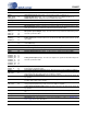
CS4207 11.ORDERING INFORMATION Product CS4207 CS4207 CDB4207 Description Package Pb-Free Low Power, 4-In/6-Out HD Audio Codec with 48L-QFN Headphone Amp Low Power, 4-In/6-Out HD Audio Codec with 48L-QFN Headphone Amp CS4207 Evaluation Board Grade Temp Range Yes Commercial -40°C to +85°C Yes Automotive -40°C to +105°C - - Container Order # Tray CS4207-CNZ Tape & Reel CS4207-CNZR Tray CS4207-DNZ Tape & Reel CS4207-DNZR - CDB4207 - 12.REFERENCES 1.
CS4207 Contacting Cirrus Logic Support For all product questions and inquiries, contact a Cirrus Logic Sales Representative. To find one nearest you, go to www.cirrus.com. IMPORTANT NOTICE Cirrus Logic, Inc. and its subsidiaries (“Cirrus”) believe that the information contained in this document is accurate and reliable. However, the information is subject to change without notice and is provided “AS IS” without warranty of any kind (express or implied).