
Manual


CS4205
DS489PP4 51
5.35 BIOS-Driver Interface Control Registers (Index 6Eh, Address 0Ch - 0Dh)
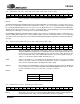
E[15:0] Event Configuration. The E[15:0] bits control the BIOS-Driver Interface mechanism.
Default 0000h
The BDI Config Register (Index 6Eh, Address 0Ch)
enables BIOS-Driver communication for each possible event. If a
bit is ‘0’, the corresponding event will not be communicated. If a bit is ‘1’, the corresponding event will be communicated
by asserting the BDI bit in input slot 12. If an event occurs, the BIOS will ‘set’ the corresponding bit in the BDI Status
Register (Index 7Ah). This bit remains ‘set’ until it is cleared by the driver, acknowledging the event has been handled.
This behavior is equivalent to “non-sticky” (level sensitive) GPIO input pins.
The BDI Wakeup Register (Index 6Eh, Address 0Dh)
provides a mask for determining if a BDI event will generate a
wakeup or GPIO_INT. If a bit is ‘0’, the corresponding event will not generate an interrupt. If a bit is ‘1’, the corresponding
event will generate an interrupt. Refer to the GPIO Pin Wakeup Mask Register (Index 52h) for details about wakeup
interrupts.
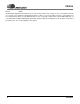
5.36 ZV Port Control/Status Registers (Index 6Eh, Address 0Eh - 0Fh)
ZVEN ZV Port Input Enable. The ZVEN bit enables the reception of asynchronous serial data on the
ZLRCLK, ZSDATA, and ZSCLK pins. The ZVEN bit routes the left and right channel data from
the ZV Port to the asynchronous SRC (ASRC) and on to the ZV volume control. This bit also func-
tions as a powerdown control for the ASRC. When this bit is ‘cleared’, the ASRC is powered
down. To use the ZV Port and the ASRC, this bit must be ‘set’.
LOCK ZV Port Locked. When ‘set’, the LOCK read-only bit indicates the ZV Port is receiving valid data
and the receiver has locked on to the data stream. If this bit is ‘cleared’, no valid data are received
on the ZV Port and the ZV input to the digital mixer will be muted.
Ph[24:0] Phase Increment. The Ph[24:0] bits contain the current Phase Increment used by the ASRC. The
current sample rate can be determined by Fs
in
= Fs
out
*Ph/16,777,216, where Fs
out
is 48 kHz.
For more information on how to use these bits see Section 7, ZV Port.
Default 0000h
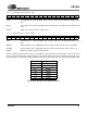
5.37 BIOS-Driver Interface Status Register (Index 7Ah)
E[15:0] Event Status. This register, in conjunction with the BIOS-Driver Interface Control Registers (In-
dex 6Eh, Address 0Ch - 0Dh), controls the BIOS-Driver Interface mechanism.
D15 D14 D13 D12 D11 D10 D9 D8 D7 D6 D5 D4 D3 D2 D1 D0
E15 E14 E13 E12 E11 E10 E9 E8 E7 E6 E5 E4 E3 E2 E1 E0
D15 D14 D13 D12 D11 D10 D9 D8 D7 D6 D5 D4 D3 D2 D1 D0
ZVEN LOCK 0 Ph24 Ph23 Ph22 Ph21 Ph20 Ph19 Ph18 Ph17 Ph16 Ph15 Ph14 Ph13 Ph12
Reserved Ph11 Ph10 Ph9 Ph8 Ph7 Ph6 Ph5 Ph4 Ph3 Ph2 Ph1 Ph0
Register Address Function
0Eh ZV Port Control/Stat 1
0Fh ZV Port Control/Stat 2
Table 21. ZV Port Control/Status Register Index
D15 D14 D13 D12 D11 D10 D9 D8 D7 D6 D5 D4 D3 D2 D1 D0
E15 E14 E13 E12 E11 E10 E9 E8 E7 E6 E5 E4 E3 E2 E1 E0