
Manual


CS4205
DS489PP4 47
5.29 Special Feature Address Register (Index 6Ch)
A[3:0] Special Feature Address. This register functions as an index register to select the desired func-
tionality of the Special Feature Data Register (Index 6Eh). Before using any of these indexed
registers, the correct index value must be written to bits A[3:0].
Default 0000h
5.30 Special Feature Data Register (Index 6Eh)
D[15:0] Special Feature Data. This register is an indexed data port for the special feature registers (In-
dex 6E, Address 00h - 0Fh) which control advanced subsystems of the CS4205, such as digital
mixer settings, effects engine parameters, ZV Port control, and internal error condition signaling.
Before using any of these functions, the correct index value must be written to the Special Fea-
ture Address Register (Index 6Ch).
Default 8000h
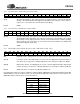
5.31 Digital Mixer Input Volume Registers (Index 6Eh, Address 00h - 05h)
Mute Digital Mixer Mute. Setting this bit mutes the respective input signal, both left and right inputs.
GL[5:0] Left Volume Control. The GL[5:0] bits are used to control the digital mixer left channel input vol-
ume. Each step corresponds to 1 dB gain adjustment. The total range is 0 dB to -63 dB gain.
GR[5:0] Right Volume Control. The GR[4:0] bits are used to control the digital mixer right channel input
volume. Each step corresponds to 1 dB gain adjustment. The total range is 0 dB to -63 dB gain.
Default 8000h. This value corresponds to 0 dB gain and Mute ‘set’.
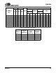
If the digital mixer signals an overflow condition by setting the MLOF or MROF bit in the IEC Status Register (Index 6Eh,
Address 0Bh), the controller should correct the error by reducing the digital mixer input volumes in these registers. The
Digital Mixer Input Volume Registers are listed in Table 17.
D15 D14 D13 D12 D11 D10 D9 D8 D7 D6 D5 D4 D3 D2 D1 D0
000000000000A3A2A1A0
D15 D14 D13 D12 D11 D10 D9 D8 D7 D6 D5 D4 D3 D2 D1 D0
D15 D14 D13 D12 D11 D10 D9 D8 D7 D6 D5 D4 D3 D2 D1 D0
D15 D14 D13 D12 D11 D10 D9 D8 D7 D6 D5 D4 D3 D2 D1 D0
Mute 0 GL5 GL4 GL3 GL2 GL1 GL0 0 0 GR5 GR4 GR3 GR2 GR1 GR0
Register Address Function
00h PCM Input Volume
01h ADC Input Volume
02h SDI1 Volume
03h SDI2 Volume
04h SDI3 Volume
05h ZV Volume
Table 17. Digital Mixer Input Volume Register Index