
Manual


CS4205
DS489PP4 27
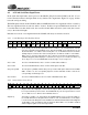
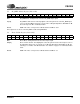
5.1 Reset Register (Index 00h)
SE[4:0] SRS 3D Stereo Enhancement. SE[4:0] = 01001, indicating this feature is present.
ID8 18-bit ADC Resolution. The ID8 bit is ‘set’, indicating this feature is present.
ID7 20-bit DAC resolution. The ID7 bit is ‘set’, indicating this feature is present.
ID5 Loudness. The ID5 bit is ‘set’, indicating this feature is present.
ID3 Simulated Stereo. The ID3 bit is ‘set’, indicating this feature is present.
ID2 Bass & Treble. The ID2 bit is ‘set’, indicating this feature is present.
ID0 Dedicated Mic PCM in Channel. The ID0 bit is ‘set’, indicating this feature is present.
Default 25ADh. The data in this register is read-only data.
Any write to this register causes a Register Reset of the audio control (Index 00h - 3Ah) and Cirrus Logic defined
(Index 5Ah - 7Ah) registers. A read from this register returns configuration information about the CS4205.
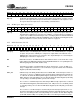
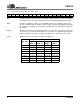
5.2 Master Volume Register (Index 02h)
Mute Master Mute. Setting this bit mutes the LINE_OUT_L/R output signals.
ML[5:0] Master Volume Left. These bits control the left master output volume. Each step corresponds
to 1.5 dB gain adjustment, with a total available range from 0 dB to -46.5 dB attenuation. Set-
ting the ML5
bit sets the left channel attenuation to -46.5 dB by forcing ML[4:0] to a ‘1’ state.
ML[5:0] will read back 011111 when ML5
has been ‘set’. See Table 4 for further details.
MR[5:0] Master Volume Right. These bits control the right master output volume. Each step corre-
sponds to 1.5 dB gain adjustment, with a total available range from 0 dB to -46.5 dB attenu-
ation. Setting the MR5
bit sets the right channel attenuation to -46.5 dB by forcing MR[4:0] to
a ‘1’ state. MR[5:0] will read back 011111 when MR5
has been ‘set’. See Table 4 for further
details.
Default 8000h. This value corresponds to 0 dB attenuation and Mute ‘set’.
D15 D14 D13 D12 D11 D10 D9 D8 D7 D6 D5 D4 D3 D2 D1 D0
0 SE4 SE3 SE2 SE1 SE0 0 ID8 ID7 0 ID5 0 ID3 ID2 0 ID0
D15 D14 D13 D12 D11 D10 D9 D8 D7 D6 D5 D4 D3 D2 D1 D0
Mute 0 ML5 ML4ML3ML2ML1ML0 0 0 MR5MR4 MR3 MR2 MR1 MR0
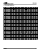
Mx5 - Mx0
Write
Mx5 - Mx0
Read
Gain
Level
000000 000000 0 dB
000001 000001 -1.5 dB
… … ...
011111 011111 -46.5 dB
100000 011111 -46.5 dB
... ... ...
111111 011111 -46.5 dB
Table 4. Analog Mixer Output Attenuation