
Instruction Manual

CS35L01/03
DS909F1 7
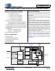
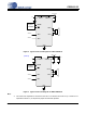
3. TYPICAL CONNECTION DIAGRAMS
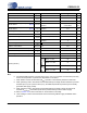
Figure 2. Typical Connection Diagram for SD & FSD Mode
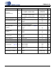
Figure 3. Typical Connection Diagram for HD & FHD Mode
Note:
3. The value of the capacitance connected to the LFILT+ net should not exceed 4.7 F. Presence of a
capacitance above 4.7 F will prevent proper HD and FHD operation.
Audio In+
Audio In-
System
Controller
GND
AIN+
AIN+
MODE
OUT+
OUT-
2.5V - 5V
VBATTLFILT+
10 uF0. 1uF
SD
1uF
0.1 uF
2.5V - 5V
10 uF
Audio In+
Audio In-
System
Controller
GND
AIN+
AIN+
MODE
OUT+
OUT-
VBATTLFILT+
SD
(Note 3)