
Instruction Manual

CS35L01/03
DS909F1 5
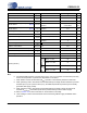
1. BALL DESCRIPTIONS FOR CS35L01 & CS35L03
Ball Name
#
Description
IN+ A1 Positive Analog Input (Input) - Differential positive audio signal input.
MODE A2 Switching Mode (Input) - Controls the output switching modes of the CS35L01/03.
OUT- A3 Negative PWM Output (Output) - Differential negative PWM output.
LFILT+ B1
Low Drop Out Regulator Filter (Output) - Bypass capacitor connection point for internal LDO. Con-
necting this net to VBATT places the device into SD mode.
VBATT B2 Positive Analog Power Supply (Input) - Positive power supply input.
GND B3 Ground (Input) - Power supply ground.
IN- C1 Negative Analog Input (Input) - Differential negative audio signal input.
SD
C2 Shutdown (Input) - Pulling this net low places the CS35L01/03 in shutdown.
OUT+ C3 Positive PWM Output (Output) - Differential Positive PWM output.
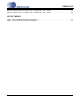
A1
IN+
A2
MODE
A3
OUT-
B1
LFILT +
B2
VBATT
B3
GND
C1
IN-
C2
SD
C3
OUT+
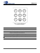
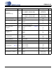
Figure 1. Top View of WLCSP Pinout
(Looking down through die)