
User guide
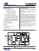

CS35L00
DS906PP1 5
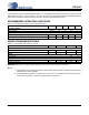
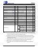
1. PIN DESCRIPTIONS FOR CS35L00
Pin Name
#
Pin Description
SD 1 Shutdown (Input) - Pulling this pin low places the CS35L00 in shutdown.
IN- 2 Negative Analog Input (Input) - Differential negative audio signal input
LFILT+ 3
Low Drop Out Regulator Filter (Output) - Bypass capacitor connection point for internal LDO. Con-
necting this net to VBATT places the device into SD mode.
IN+ 4 Positive Analog Input (Input) - Differential positive audio signal input.
MODE 5 Switching Mode (Input) - Controls the output switching modes of the CS35L00.
OUT- 6 Negative PWM Output (Output) - Differential negative PWM output.
GAIN_SEL 7
Gain Select (Input) - Sets the gain of the amplifier. When pulled low, gain is +12 dB. When pulled high,
gain is +6 dB.
VBATT 8 Positive Analog Power Supply (Input) - Positive power supply input.
GND 9 Ground (Input) - Power supply ground.
OUT+ 10 Positive PWM Output (Output) - Differential Positive PWM output.
Thermal Pad -
Thermal Pad (Input) - Thermal relief pad for optimized heat dissipation. Connect to GND. See “DFN
Thermal Pad” on page 31 for more information.
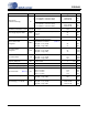
1
2
3
4
5
10
9
8
7
6
Thermal Pad
SD
IN-
LFILT+
IN+
MODE
OUT+
GND
VBATT
GAIN_SEL
OUT-
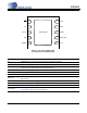
Figure 1. Top View of DFN Pin Out
(Looking down through package)