
User guide


CS35L00
24 DS906PP1
Note:
17. “Idle Current Draw vs. VBATT - FSD Mode” capacitor values refer to C
FILT
when configured as the
“CS35L00’s Minimized Optional Output Filter”, shown in Figure 5 on page 17.
0.0
0.5
1.0
1.5
2.0
2.5
3.0
3.5
2.5 3.0 3.5 4.0 4.5 5.0 5.5
Output Power (W)
VBATT Supply Voltage (V)
0.00
0.50
1.00
1.50
2.00
2.50
3.00
3.50
2.5 3 3.5 4 4.5 5 5.5
Idle Current Draw (mA)
VBATT Supply Voltage (V)
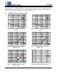
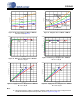
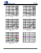
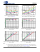
Figure 26. Idle Current Draw vs. VBATT - FSD Mode
R
L
=8Ω +33μH (Note 17)
Figure 27. Output Power vs. VBATT - FSD Mode
R
L
= 8 Ω
1% THD+N Ratio
R
L
= 8 Ω
10% THD+N Ratio
R
L
= 4 Ω
1% THD+N Ratio
R
L
= 4 Ω
10% THD+N Ratio
470 pF
No Filter
1000 pF
2200 pF
0%
10%
20%
30%
40%
50%
60%
70%
80%
90%
100%
0 250 500 750 1000 1250 1500 1750 2000
Efficiency (%)
Output Power (mW)
0%
10%
20%
30%
40%
50%
60%
70%
80%
90%
100%
0 500 1000 1500 2000 2500 3000 3500
Efficiency (%)
Output Power (mW)
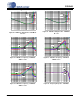
Figure 28. Efficiency vs. Output Power - FSD Mode
R
L
=8Ω +33μH
Figure 29. Efficiency vs. Output Power - FSD Mode
R
L
=4Ω +33μH
4.2 V
3.7 V
5.0 V
4.2 V
3.7 V
5.0 V
0
50
100
150
200
250
300
350
400
450
0 250 500 750 1000 1250 1500 1750 2000
Current Consumption (mA)
Output Power (mW)
0
100
200
300
400
500
600
700
800
0 500 1000 1500 2000 2500 3000 3500
Current Consumption (mA)
Output Power (mW)
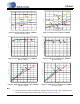
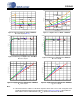
Figure 30. Supply Current vs. Output Power - FSD Mode
R
L
=8Ω +33μH
Figure 31. Supply Current vs. Output Power - FSD Mode
R
L
=4Ω +33μH
5.0 V
4.2 V
3.7 V
5.0 V
4.2 V
3.7 V