
User guide

34 DS702F1
CS3308
7.4.3 Channel B = Channel A (Bit 0 - 3)
Default = 0
Function:
When this bit is set, Channel A and Channel B volume levels and muting conditions are controlled by
the Channel A volume and muting register settings, and the Channel B register settings are ignored.
When this bit is cleared, Channel A and Channel B volume and mute settings are independently con-
trolled by the A and B volume and muting bits.
7.5 Device Configuration 2 - Address 0Ch
7.5.1 Zero-Crossing Time-Out Period (Bits 4:2)
Default = 011
Function:
These bits set the zero-crossing time-out period as shown in Table 9. Refer to the “Zero-Crossing
Time-Out” section on page 22 for more information.
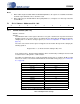
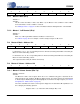
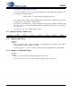
Bit Name Bit Setting Control Configuration
Ch8=7 0 Channel 7 and 8 mute and volume settings controlled independently
1 Channel 7 and 8 mute and volume settings controlled by Channel 7 register
settings. Channel 8 register settings are ignored.
Ch6=5 0 Channel 5 and 6 mute and volume settings controlled independently
1 Channel 5 and 6 mute and volume settings controlled by Channel 5 register
settings. Channel 6 register settings are ignored.
Ch4=3 0 Channel 3 and 4 mute and volume settings controlled independently
1 Channel 3 and 4 mute and volume settings controlled by Channel 3 register
settings. Channel 4 register settings are ignored
Ch2=1 0 Channel 1 and 2 mute and volume settings controlled independently
1 Channel 1 and 2 mute and volume settings controlled by Channel 1 register
settings. Channel 2 register settings are ignored
Table 7. Channel B = Channel A Settings
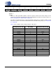
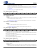
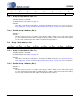
76543210
Reserved Reserved Reserved TimeOut2 TimeOut1 TimeOut0 ZCMode1 ZCMode0
TimeOut[2:0]
Zero-Crossing
Time-Out Period
000 5 ms
001 10 ms
010 15 ms
011 18 ms
100 20 ms
101 30 ms
110 40 ms
111 50 ms
Table 8. Zero-Crossing Time-Out Settings