
User guide

DS702F1 31
CS3308
7. CS3308 REGISTER DESCRIPTIONS
Notes:
1. When addressing the CS3308 with the Individual Chip Address, all registers are read/write in I²C Mode
and write-only in SPI Mode, unless otherwise noted.
2. When addressing the CS3308 with the Group Chip Addresses, all registers are write-only in both I²C
and SPI Mode.
7.1 Ch 1-8 Volume - Addresses 01h - 08h
7.1.1 Volume Control (Bits 7:0)
Default = 11010010
Function:
The individual volume control registers allow the user to gain or attenuate the respective channels in
0.5 dB increments. The volume changes are implemented as dictated by the ZCMode[1:0] and Tim-
eOut[2:0] bits in the Device Config 2 register (see “Device Configuration 2 - Address 0Ch” on
page 34).
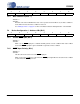
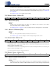
The value of the Volume Control register is mapped to the desired 0.5 dB step volume setting by the
following equation:
In the equation above, “Desired Volume Setting in dB” is determined by rounding the desired ¼ dB
resolution volume setting down to ½ dB resolution.
It should be noted that input values outside the CS3308’s analog range of +22 dB to -96 dB are valid,
however, the volume of each channel will be limited to the CS3308’s analog range (see “Volume Lim-
its” on page 20).
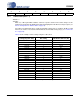
76543210
Vol7 Vol6 Vol5 Vol4 Vol3 Vol2 Vol1 Vol0
Register Setting Gain or Attenuation (dB)*
11111110 +22
11111101 +21.5
11111100 +21
--
11010100 +1
11010011 +0.5
11010010 0
11010001 -0.5
11010000 -1
--
00010100 -95
00010011 -95.5
00010010 -96
* QuarterX = ‘0’. See “¼ dB Control (Bit 0 - 7)” on page 32.
Table 5. Example Volume Settings
Register Value 2 Desired Volume Setting in dB×()210+=