
User guide


CS3301A
12 DS757F1
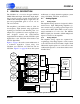
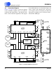
2.4 Connection Diagram
Figure 5 on page 12 shows a connection diagram
for the CS3301A amplifier when used with the
CS5372A dual ∆Σ modulator, the CS4373A Test
DAC, and the CS5376A digital filter. The diagram
shows differential sensors and test DAC inputs, and
analog outputs with anti-alias RC components;
power supply connections including recommended
bypassing; and digital control connections back to
the CS5376A GPIO pins.
0.02µF
C0G
0.02µF
C0G
0.02µF
C0G
0.02µF
C0G
CS5372A
∆Σ Modulator
INF+
INR+
INF-
INR-
INF-
INR-
INF+
INR+
VREF+
VREF-
VA+
VA-
VD
GND
MDATA1
MFLAG1
MDATA2
MFLAG2
MCLK
MSYNC
PWDN1
OFST
PWDN2
CS3301A
Differential
Amplifier
INB+INA+ INA- INB- OUTF-OUTR- OUTF+ OUTR+
VA+
VA-
VD
GND
CLKGAIN MUX PWDN
CS3301A
Differential
Amplifier
INB+INA+ INA- INB- OUTF-OUTR- OUTF+ OUTR+
VA+
VA-
VD
GND
CLKGAIN MUX PWDN
VA-
0.1µF
VA+
0.1µF
VA-
0.1µF
VA+
0.1µF
VD
0.01µF
VD
0.01µF
MCLK
GPIO
GPIO (x2)
GPIO (x3)
MCLK
GPIO
GPIO (x2)
GPIO (x3)
Differential
Sensor
Differential
Sensor
CS4373A
Test DAC
3
2
3
2
To CS5376A
Digital Control
To CS5376A
Digital Control
2.5 V
Reference
VA+
0.1µF 0.01µF
VD
VA-
0.1µF
680
680
680
680
680
680
680
680
Figure 5. CS3301A Amplifier Connections