
Manual

CS3002
DS490F10 9
3.2 Open-loop Gain and Stability
3.2.1 Discussion
The CS3002 achieves ultra-high open-loop gain.
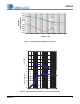
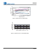
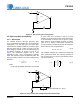
Figure 14 illustrates the amplifier in a non-inverting gain
configuration. The open-loop gain and phase plots
indicate that the amplifier is stable for closed-loop gains
less than 50V/V and R1 100
. For a gain of 50, the
phase margin is between 40 and 60 depending upon
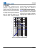
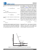
the loading conditions. As shown in Figure 15, on
page 9, the operational amplifier has an input
capacitance at the + and – signal inputs of typically
50pF. This capacitance adds an additional pole in the
loop gain transfer function at a frequency defined using
Equation 1:
where
R = R1 R2; the parallel combination of R1 and R2
A higher value for R produces a pole at a lower
frequency, thus reducing the phase margin. Resistor R1
is recommended to be less than or equal to 100
,
which results in a pole at 30MHz or higher. If a higher
value of R1 is desired, compensation capacitor C2
should be added in parallel with resistor R2. Capacitor
C2 should be chosen using Equation 2:
The feedback capacitor C2 is required for closed-loop
gains greater than 50V/V. The capacitor introduces a
pole P
1
and a zero Z
1
in the loop gain transfer function
T(s), see Equation 3
f
1
2RC
in
--------------------------
=
[Eq. 1]
R2 C2 R1 C
in
[Eq. 2]
R1
R2
Vin
Vo
R
S
CS3002
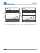
Figure 14. Non-inverting Gain Configuration
50 pF
50 pF
R1
R2
Vin
Vo
C2
C
in
C
in
Choose C2 so that R2 C2
R1 C
in
CS3002
Figure 15. Non-inverting Gain Configuration with Compensation
Ts
1
s
Z
1
------
+
–
1
s
P
1
------
+
------------------------ -
A
ol
=
[Eq. 3]