
Manual

CS2300-CP
DS843F2 5
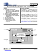
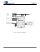
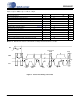
2. TYPICAL CONNECTION DIAGRAM
GND
SCL/CCLK
SDA/CDIN
2 kΩ
Frequency Reference CLK_IN
CLK_OUT
AUX_OUT
0.1 µF
VD
+3.3 V
Notes:
1. Resistors
required for I
2
C
operation.
2 kΩ
AD0/CS
System MicroController
1 µF
Note
1
To circuitry which requires
a low-jitter clock
To other circuitry or
Microcontroller
FILTP
FILTN
0.1 µF
Figure 1. Typical Connection Diagram
CS2300-CP