
Manual

CS2300-CP
18 DS843F2
Ratio modifiers which would produce an overflow or truncation of R
EFF
should not be used; For example
if R
UD
is 1024 an R
MOD
of 8 would produce an R
EFF
value of 8192 which exceeds the 4096 limit of the
12.20 format. In all cases, the maximum and minimum allowable values for R
EFF
are dictated by the fre-
quency limits for both the input and output clocks as shown in the “AC Electrical Characteristics” on
page 7.
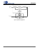
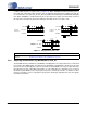
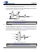
5.3.4 Ratio Configuration Summary
The R
UD
is the user defined ratio stored in the register space. The resolution for the R
UD
is selectable by
setting LFRatioCfg. R-Mod is applied if selected. The user defined ratio, and ratio modifier make up the
effective ratio R
EFF
, the final calculation used to determine the output to input clock ratio. The conceptual
diagram in Figure 15 summarizes the features involved in the calculation of the ratio values used to gen-
erate the fractional-N value which controls the Frequency Synthesizer.
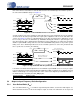
Figure 15. Ratio Feature Summary
Referenced Control Register Location
Ratio......................................“Ratio (Address 06h - 09h)” on page 26
LFRatioCfg............................“Low-Frequency Ratio Configuration (LFRatioCfg)” on page 28
RModSel[2:0] ........................“R-Mod Selection (RModSel[2:0])” section on page 25
Effective Ratio R
EFF
Ratio Format
Frequency Reference Clock
(CLK_IN)
PLL Output
Frequency
Synthesizer
Digital PLL &
Fractional N Logic
N
Ratio
12.20
20.12
LFRatioCfg
RModSel[2:0]
Ratio
Modifier
LCO
User Defined Ratio R
UD