
Instruction Manual

CS2200-OTP
20 DS842F2
7. CALCULATING THE USER DEFINED RATIO
Note: The software for use with the evaluation kit has built in tools to aid in calculating and converting the User
Defined Ratio. This section is for those who would like to know more about how the User Defined Ratio is
calculated and stored.
Most calculators do not interpret the fixed point binary representation which the CS2200-OTP uses to define the
output to input clock ratio (see Section 5.3.1 on page 11); However, with a simple conversion we can use these tools
to generate a binary or hex value for Ratio
0-3
to be stored in one time programmable memory. Please see “Program-
ming Information” on page 21 for more details on programming.
7.1 12.20 Format
To calculate the User Defined Ratio (R
UD
) to store in the register(s), divide the desired output clock frequen-
cy by the given input clock (RefClk). Then multiply the desired ratio by the scaling factor of 2
20
to get the
scaled decimal representation; then use the decimal to binary/hex conversion function on a calculator and
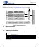
write to the register. A few examples have been provided in Table 3.
Table 3. Example 12.20 R-Values
Desired Output to Input Clock Ratio
(output clock/input clock)
Scaled Decimal
Representation =
(output clock/input clock)
• 2
20
Hex Representation of
Binary R
UD
12.288 MHz/10 MHz=1.2288
1288490 00 13 A9 2A
11.2896 MHz/44.1 kHz=256
268435456 10 00 00 00