
Instruction Manual

CS2200-OTP
DS842F2 17
6. PARAMETER DESCRIPTIONS
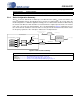
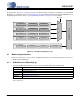
As mentioned in Section 5.1 on page 9, there are two different kinds of parameter configuration sets, Modal and
Global. These configuration sets, shown in Figure 10, can be programmed in the field using the CDK2000 or pre-
programmed at the factory. Please see “Programming Information” on page 21 for more details.
Figure 10. Parameter Configuration Sets
6.1 Modal Configuration Sets
There are four instances of each of these configuration parameters. Selection between the four stored sets
is made using the M[1:0] pins.
6.1.1 R-Mod Selection (RModSel[1:0])
Selects the R-Mod value, which is used as a factor in determining the PLL’s Fractional N.
Note: This parameter does not take affect unless M2 pin is high and the M2Config[2:0] global param-
eter is set to ‘011’.
RModSel[1:0] R-Mod Selection
00 Right-shift R-value by 1 (÷ 2).
01 Right-shift R-value by 2 (÷ 4).
10 Right-shift R-value by 3 (÷ 8).
11 Right-shift R-value by 4 (÷ 16).
Application: “Ratio Modifier (R-Mod)” on page 11
M[1:0] pins
Modal Configuration Set #0
RModSel[1:0] AuxOutSrc[1:0]
Modal Configuration Set #1
Ratio 1 RModSel[1:0] AuxOutSrc[1:0]
Modal Configuration Set #2
Ratio 2 RModSel[1:0] AuxOutSrc[1:0]
Modal Configuration Set #3
Ratio 3 RModSel[1:0] AuxOutSrc[1:0]
00
01
10
11
Global Configuration Set
RefClkDiv[1:0] ClkOutUnlAuxLockCfg M2Config[2:0]
Ratio 0
Digital/PLL Core